Products Category
- FM Transmitter
- 0-50w 50w-1000w 2kw-10kw 10kw+
- TV Transmitter
- 0-50w 50-1kw 2kw-10kw
- FM Antenna
- TV Antenna
- Antenna Accessory
- Cable Connector Power Splitter Dummy Load
- RF Transistor
- Power Supply
- Audio Equipments
- DTV Front End Equipment
- Link System
- STL system Microwave Link system
- FM Radio
- Power Meter
- Other Products
- Special for Coronavirus
Products Tags
Fmuser Sites
- es.fmuser.net
- it.fmuser.net
- fr.fmuser.net
- de.fmuser.net
- af.fmuser.net ->Afrikaans
- sq.fmuser.net ->Albanian
- ar.fmuser.net ->Arabic
- hy.fmuser.net ->Armenian
- az.fmuser.net ->Azerbaijani
- eu.fmuser.net ->Basque
- be.fmuser.net ->Belarusian
- bg.fmuser.net ->Bulgarian
- ca.fmuser.net ->Catalan
- zh-CN.fmuser.net ->Chinese (Simplified)
- zh-TW.fmuser.net ->Chinese (Traditional)
- hr.fmuser.net ->Croatian
- cs.fmuser.net ->Czech
- da.fmuser.net ->Danish
- nl.fmuser.net ->Dutch
- et.fmuser.net ->Estonian
- tl.fmuser.net ->Filipino
- fi.fmuser.net ->Finnish
- fr.fmuser.net ->French
- gl.fmuser.net ->Galician
- ka.fmuser.net ->Georgian
- de.fmuser.net ->German
- el.fmuser.net ->Greek
- ht.fmuser.net ->Haitian Creole
- iw.fmuser.net ->Hebrew
- hi.fmuser.net ->Hindi
- hu.fmuser.net ->Hungarian
- is.fmuser.net ->Icelandic
- id.fmuser.net ->Indonesian
- ga.fmuser.net ->Irish
- it.fmuser.net ->Italian
- ja.fmuser.net ->Japanese
- ko.fmuser.net ->Korean
- lv.fmuser.net ->Latvian
- lt.fmuser.net ->Lithuanian
- mk.fmuser.net ->Macedonian
- ms.fmuser.net ->Malay
- mt.fmuser.net ->Maltese
- no.fmuser.net ->Norwegian
- fa.fmuser.net ->Persian
- pl.fmuser.net ->Polish
- pt.fmuser.net ->Portuguese
- ro.fmuser.net ->Romanian
- ru.fmuser.net ->Russian
- sr.fmuser.net ->Serbian
- sk.fmuser.net ->Slovak
- sl.fmuser.net ->Slovenian
- es.fmuser.net ->Spanish
- sw.fmuser.net ->Swahili
- sv.fmuser.net ->Swedish
- th.fmuser.net ->Thai
- tr.fmuser.net ->Turkish
- uk.fmuser.net ->Ukrainian
- ur.fmuser.net ->Urdu
- vi.fmuser.net ->Vietnamese
- cy.fmuser.net ->Welsh
- yi.fmuser.net ->Yiddish
What is Direct Digital Synthesiser DDS
- A tutorial giving information about the basics of the direct digital synthesizer, DDS and the advantages of these synthesizers for RF applications.
Direct digital synthesis (DDS) is a powerful technique used in the generation of radio frequency signals for use in a variety of applications from radio receivers to signals generators and many more. The technique has become far more widespread in recent years with the advances being made in integrated circuit technology that allow much faster speeds to be handled which in turn enable higher frequency DDS chips to be made.
How DDS works
As the name suggests this form of synthesis generates the waveform directly using digital techniques. This is different to the way in which the more familiar indirect synthesizers that use a phase locked loop as the basis of their operation.
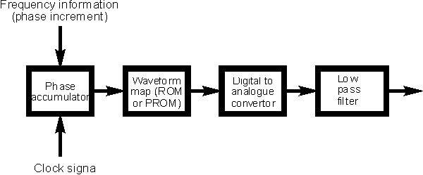
A direct digital synthesizer operates by storing the points of a waveform in digital format, and then recalling them to generate the waveform. The rate at which the synthesizer completes one waveform then governs the frequency. The overall block diagram is shown below, but before looking at the details operation of the synthesizer it is necessary to look at the basic concept behind the system.
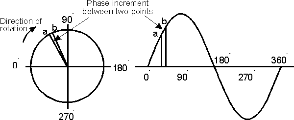
The operation can be envisaged more easily by looking at the way that phase progresses over the course of one cycle of the waveform. This can be envisaged as the phase progressing around a circle. As the phase advances around the circle, this corresponds to advances in the waveform.

Block Diagram of a Basic Direct Digital Synthesizer (DDS)
The synthesizer operates by storing various points in the waveform in digital form and then recalling them to generate the waveform. Its operation can be explained in more detail by considering the phase advances around a circle as shown in Figure 2. As the phase advances around the circle this corresponds to advances in the waveform, i.e. the greater the number corresponding to the phase, the greater the point is along the waveform. By successively advancing the number corresponding to the phase it is possible to move further along the waveform cycle.

Operation of the phase accumulator in a direct digital synthesizer
Once the phase has been determined it is necessary to convert this into a digital representation of the waveform. This is accomplished using a waveform map. This is a memory which stores a number corresponding to the voltage required for each value of phase on the waveform. In the case of a synthesizer of this nature it is a sine look up table as a sine wave is required. In most cases the memory is either a read only memory (ROM) or programmable read only memory (PROM). This contains a vast number of points on the waveform, very many more than are accessed each cycle. A very large number of points is required so that the phase accumulator can increment by a certain number of points to set the required frequency.
The next stage in the process is to convert the digital numbers coming from the sine look up table into an analogue voltage. This is achieved using a digital to analogue converter (DAC). This signal is filtered to remove any unwanted signals and amplified to give the required level as necessary.
Tuning is accomplished by increasing or decreasing the size of the step or phase increment between different sample points. A larger increment at each update to the phase accumulator will mean that the phase reaches the full cycle value faster and the frequency is correspondingly high. Smaller increments to the phase accumulator value means that it takes longer to increase the full cycle value and a correspondingly low value of frequency. In this way it is possible to control the frequency. It can also be seen that frequency changes can be made instantly by simply changing the increment value. There is no need to a settling time as in the case of phase locked loop based synthesizer.
From this it can be seen that there is a finite difference between one frequency and the next, and that the minimum frequency difference or frequency resolution is determined by the total number of points available in the phase accumulator. A 24 bit phase accumulator provides just over 16 million points and gives a frequency resolution of about 0.25 Hz when used with a 5 MHz clock. This is more than adequate for most purposes.

