
Products Category
- FM Transmitter
- 0-50w 50w-1000w 2kw-10kw 10kw+
- TV Transmitter
- 0-50w 50-1kw 2kw-10kw
- FM Antenna
- TV Antenna
- Antenna Accessory
- Cable Connector Power Splitter Dummy Load
- RF Transistor
- Power Supply
- Audio Equipments
- DTV Front End Equipment
- Link System
- STL system Microwave Link system
- FM Radio
- Power Meter
- Other Products
- Special for Coronavirus
Products Tags
Fmuser Sites
- es.fmuser.net
- it.fmuser.net
- fr.fmuser.net
- de.fmuser.net
- af.fmuser.net ->Afrikaans
- sq.fmuser.net ->Albanian
- ar.fmuser.net ->Arabic
- hy.fmuser.net ->Armenian
- az.fmuser.net ->Azerbaijani
- eu.fmuser.net ->Basque
- be.fmuser.net ->Belarusian
- bg.fmuser.net ->Bulgarian
- ca.fmuser.net ->Catalan
- zh-CN.fmuser.net ->Chinese (Simplified)
- zh-TW.fmuser.net ->Chinese (Traditional)
- hr.fmuser.net ->Croatian
- cs.fmuser.net ->Czech
- da.fmuser.net ->Danish
- nl.fmuser.net ->Dutch
- et.fmuser.net ->Estonian
- tl.fmuser.net ->Filipino
- fi.fmuser.net ->Finnish
- fr.fmuser.net ->French
- gl.fmuser.net ->Galician
- ka.fmuser.net ->Georgian
- de.fmuser.net ->German
- el.fmuser.net ->Greek
- ht.fmuser.net ->Haitian Creole
- iw.fmuser.net ->Hebrew
- hi.fmuser.net ->Hindi
- hu.fmuser.net ->Hungarian
- is.fmuser.net ->Icelandic
- id.fmuser.net ->Indonesian
- ga.fmuser.net ->Irish
- it.fmuser.net ->Italian
- ja.fmuser.net ->Japanese
- ko.fmuser.net ->Korean
- lv.fmuser.net ->Latvian
- lt.fmuser.net ->Lithuanian
- mk.fmuser.net ->Macedonian
- ms.fmuser.net ->Malay
- mt.fmuser.net ->Maltese
- no.fmuser.net ->Norwegian
- fa.fmuser.net ->Persian
- pl.fmuser.net ->Polish
- pt.fmuser.net ->Portuguese
- ro.fmuser.net ->Romanian
- ru.fmuser.net ->Russian
- sr.fmuser.net ->Serbian
- sk.fmuser.net ->Slovak
- sl.fmuser.net ->Slovenian
- es.fmuser.net ->Spanish
- sw.fmuser.net ->Swahili
- sv.fmuser.net ->Swedish
- th.fmuser.net ->Thai
- tr.fmuser.net ->Turkish
- uk.fmuser.net ->Ukrainian
- ur.fmuser.net ->Urdu
- vi.fmuser.net ->Vietnamese
- cy.fmuser.net ->Welsh
- yi.fmuser.net ->Yiddish
How to Select, Use, and Maintain Coaxial Connectors for RF Applications?
Radio frequency (RF) circuits are proliferating in both wired and wireless communications, including Wi-Fi and various wireless technologies being used for the Internet of Things (IoT). These high-frequency signals need to be distributed between systems, circuit components, and subassemblies with minimum loss or spurious radiation.
While this is traditionally the role of the RF coaxial cables and connectors, designers under time, cost, and reliability pressure need to make sure they quickly pick the optimum RF connector and apply it correctly for maximum performance and long life.
This article will view RF connectors from the perspective of critical parameters such as size, frequency range, loss, and durability to help designers match their connector to their RF application. It will also present suitable solutions with useful information on how to apply and maintain them.
RF coaxial connectors
RF coaxial connectors and cables provide key RF links in communications, broadcast, and wireless, as well as test and measurement usage. They provide low-loss paths between RF systems, components, subassemblies, and devices utilizing coaxial cable or strip lines. The basic coaxial structure consists of a central conductor surrounded by a concentric insulating dielectric layer. This is, in turn, enclosed by a cylindrical conductive shell. The dimensions of the cable elements are controlled precisely to give a constant conductor dimension and spacing, which is needed for it to function efficiently as a transmission line.
RF connectors provide junctions for joining coaxial cables and strip line transmission lines to other components or subassemblies. They extend the coaxial structure adding interlocking conductors along with a locking mechanism, all while maintaining a constant electrical impedance. A mating pair of subminiature type A (SMA) connector elements from Amphenol RF is shown in Figure 1.
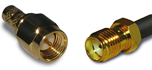
The left hand image is the male or plug half. The right hand image shows the female, jack or receptacle half of the connector pair. In general, the plug will have a protruding center conductor and internal locking threads on the outer conductor. The receptacle has a recessed inner conductor and external locking threads. It should be noted that some ‘reverse-polarity‘ connector types will have the locking threads reversed, with external threads on the male component and internal threads on the female component. Other locking mechanisms may include twist lock, bayonet connection, or snap-lock rings.
Most coaxial connectors, like this SMA connector pair are ‘sexed’, having different structures on each half. There are some connectors which have identical structures on each side of the junction. These are mostly high precision connectors intended for laboratory applications.
Coaxial connector types
While there are a myriad of RF connectors, they are differentiated by a number of key parameters. These specifications include physical size, impedance, VSWR, coupling type, and bandwidth or frequency range (Table 1).
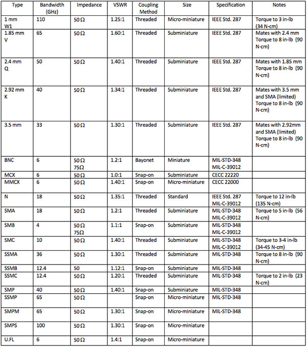
Table 1: Summary table of commonly used coaxial connector specifications
The key specification for a coaxial connector is its bandwidth. This describes the highest frequency at which it can be used. A connector’s maximum usable frequency is a function of the diameter of the outer shell and the material used as a dielectric. The smaller the shell diameter, the higher the maximum usable frequency. Similarly, using air as the dielectric offers the highest frequency performance relative to other dielectrics. As a result, the highest bandwidth connectors use air as a dielectric.
Connector impedance
To ensure maximum power transfer and reduce power loss due to reflections, the characteristic impedance of the connector should match the source and load. Most connectors for general RF applications are designed to present a 50 W impedance; while 75 W connectors are available for video-related applications.
VSWR
The voltage standing wave ratio (VSWR) is a measure of the effective impedance of the mated connector. The higher the VSWR, the more power is reflected from the connector due to impedance mismatches. Note that VSWR is a function of frequency, and connector VSWR values should only be compared at the same frequency.
Coupling mechanism
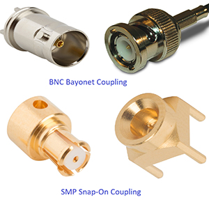
The coupling column lists the type of mechanical locking mechanism employed. This is extremely important in applications where the connector is to be subject to vibration. Coupling is normally a tradeoff between ease of connection and secure locking. The SMA connector pair shown previously in Figure 1 is an example of a threaded coupling. Examples of the bayonet and snap-on coupling are illustrated in Figure 2, using the BNC and SMP connector type, respectively.
Connector size and durability
Given the trend toward miniaturization, size plays a major role in selecting a connector. Table 2, again, shows the size classes of the listed connectors. There is a trade-off between size and connector lifetime. Smaller connectors tend to have fewer available connect/disconnect mating cycles. Where the larger N connector may have a durability of greater than 500 mating cycles, the micro miniature U.FL connector durability is limited to 30 mating cycles. The lifetime of every connector varies with the manufacturer, and their specifications should be consulted if lifetime is an important parameter.
Coaxial connectors used in applications like test and measurement instruments, where many mating cycles are typical, are generally protected by the use of ‘connector savers.’ These easily replaced adaptors mate with the instrument connectors and present an expendable connector body for multiple uses.
Connector class and industry specifications
Connectors are categorized by several differing classes. In Table 2, precision connectors such as the 1 mm through 2.92 mm and N connectors fall under the IEEE-STD-287. These connectors have more precise dimensional tolerances dictated by their wide bandwidth applications. The more common connectors fall under MIL-STD-348 or under one of the European standards, such as CECC 22220. Tolerances on these connectors are looser so there’s an opportunity to save on cost.
Mating compatibility
Related to the connector class is the ability to mate connectors from various families. Table 2 lists a number of possible interchangeable connector matings. The 1.85 mm and 2.4 mm connectors are interchangeable, as are the 2.92 mm and 3.5 mm connectors. The 2.92 mm and 3.5 mm male connector bodies can mate with SMA female connectors with a reduction in the overall bandwidth. Due to the difference in their tolerance class, it is not a good practice to try to mate an SMA male with either a 2.92 mm or 3.5 mm female connector. The broader mechanical tolerances of the SMA may damage the receptacle pins of the precision connectors.
Connector power rating
Manufacturers do not rate the power dissipation of their connectors because that specification is very application dependent. It varies according to frequency, system VSWR, temperature, altitude, and load impedances. In general, the power handling varies directly with the connector’s size and heat dissipation capability. Maximum power dissipation decreases with increasing frequency.
The connector with the best power handling capability is the N connector, which is able to handle 300 and 400 watts (W). The BNC and SMA connectors would follow in order. Precision connectors are limited to 10s of Watts. Again, if high power operation is required, it is important to contact the manufacturer for more precise power dissipation specifications.
Connector usage
Before using a connector, it is important to inspect it for damage such as metal particles, bent center conductors, or crushed or deformed outer shells (Figure 3). Any damage should be repaired, or the impaired connector should be replaced. Connectors should be clean with no accumulated dirt or other contaminants. Connector bodies should mate smoothly with no sticking or jamming. Do not force connector mating; if a problem occurs, re-inspect the connector to determine the source.
When mating a threaded connector, turn only the outer shell and not the connector body or cable. Rotating the connector body may damage the center conductors. Once the outer ferrule is hand tight, use a calibrated torque wrench to attain the specified locking torque per the manufacturer’s instructions.
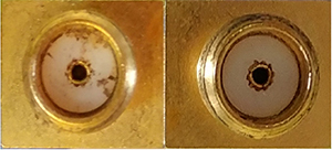
Figure 3: (left) An example of an SMA connector with dirt and metal filings accumulated on the dielectric, (right) the same connector after being cleaned with a cotton swab and isopropyl alcohol.
Connector maintenance
Connectors should be kept clean. The best way to insure this is to use protective caps on connectors when they are not in use. If a connector is contaminated by dirt it should be cleaned. Connectors with solid dielectrics can be cleaned with a lint free cotton swab dipped in isopropyl alcohol. Be careful to avoid bending center conductor pins. It is a good practice to also clean the threads, both internal and external on threaded connectors. Do not use a swab on connectors which use an air dielectric, as the dielectric beads which hold the elements in place can be damaged by solvents. They can be cleaned using dry compressed air.
Selecting coaxial connectors
Selecting a coaxial connector starts with the bandwidth required to handle the signals being used, followed by the considerations of size and mechanical configuration (plug, receptacle, solder in, panel mount, etc.). For example, consider the output connector for a 1 GHz signal generator. Since this is a test and measurement signal source, the BNC connector is a common choice. The bandwidth of the BNC is greater than 1 GHz and it is available as a panel mounted receptacle.
When selecting a connector for a frequency signal in excess of 10 GHz, consider an SMA connector. This choice might be governed by the tradeoff between bandwidth and cost. The 2.9 mm connector has greater than twice the bandwidth of the SMA, but that bandwidth advantage comes at almost three times the cost.
Conclusion
This article has reviewed the range of RF coaxial connectors summarizing their primary attributes. It represents a good starting point for designers in selecting a suitable connector for their design. As shown, careful review of the engineering requirements is important when selecting a seemingly simple RF coaxial connector.
If you are looking for RF L27 Male coaxial connector, please click the link: http://fmuser.net/content/?693.html
