Products Category
- FM Transmitter
- 0-50w 50w-1000w 2kw-10kw 10kw+
- TV Transmitter
- 0-50w 50-1kw 2kw-10kw
- FM Antenna
- TV Antenna
- Antenna Accessory
- Cable Connector Power Splitter Dummy Load
- RF Transistor
- Power Supply
- Audio Equipments
- DTV Front End Equipment
- Link System
- STL system Microwave Link system
- FM Radio
- Power Meter
- Other Products
- Special for Coronavirus
Products Tags
Fmuser Sites
- es.fmuser.net
- it.fmuser.net
- fr.fmuser.net
- de.fmuser.net
- af.fmuser.net ->Afrikaans
- sq.fmuser.net ->Albanian
- ar.fmuser.net ->Arabic
- hy.fmuser.net ->Armenian
- az.fmuser.net ->Azerbaijani
- eu.fmuser.net ->Basque
- be.fmuser.net ->Belarusian
- bg.fmuser.net ->Bulgarian
- ca.fmuser.net ->Catalan
- zh-CN.fmuser.net ->Chinese (Simplified)
- zh-TW.fmuser.net ->Chinese (Traditional)
- hr.fmuser.net ->Croatian
- cs.fmuser.net ->Czech
- da.fmuser.net ->Danish
- nl.fmuser.net ->Dutch
- et.fmuser.net ->Estonian
- tl.fmuser.net ->Filipino
- fi.fmuser.net ->Finnish
- fr.fmuser.net ->French
- gl.fmuser.net ->Galician
- ka.fmuser.net ->Georgian
- de.fmuser.net ->German
- el.fmuser.net ->Greek
- ht.fmuser.net ->Haitian Creole
- iw.fmuser.net ->Hebrew
- hi.fmuser.net ->Hindi
- hu.fmuser.net ->Hungarian
- is.fmuser.net ->Icelandic
- id.fmuser.net ->Indonesian
- ga.fmuser.net ->Irish
- it.fmuser.net ->Italian
- ja.fmuser.net ->Japanese
- ko.fmuser.net ->Korean
- lv.fmuser.net ->Latvian
- lt.fmuser.net ->Lithuanian
- mk.fmuser.net ->Macedonian
- ms.fmuser.net ->Malay
- mt.fmuser.net ->Maltese
- no.fmuser.net ->Norwegian
- fa.fmuser.net ->Persian
- pl.fmuser.net ->Polish
- pt.fmuser.net ->Portuguese
- ro.fmuser.net ->Romanian
- ru.fmuser.net ->Russian
- sr.fmuser.net ->Serbian
- sk.fmuser.net ->Slovak
- sl.fmuser.net ->Slovenian
- es.fmuser.net ->Spanish
- sw.fmuser.net ->Swahili
- sv.fmuser.net ->Swedish
- th.fmuser.net ->Thai
- tr.fmuser.net ->Turkish
- uk.fmuser.net ->Ukrainian
- ur.fmuser.net ->Urdu
- vi.fmuser.net ->Vietnamese
- cy.fmuser.net ->Welsh
- yi.fmuser.net ->Yiddish
The Radio Communication-1
1. HIGH-FREQUENCY RADIO FUNDAMENTALS
For successful communication , HF radio performance depends on the type of emission (voice or burst device), transmitter power output, and type of antenna. The challenge facing HF radio operators is tremendous. They must use their HF radio systems to transmit important information to the DOB or AOB. The HF radio operator must continually adjust his system to compensate for changing conditions and missions. Knowledgeable operators, properly constructed antennas, and propagated frequencies are the key to successful, effective HF radio communication.
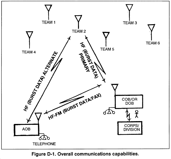
A. Of the variables that affect HF radio communication, the antenna is the one that an operator has the most control over. Proper antenna use greatly increases the chances of effective communication. Achieving the NVIS (near vertical incidence sky-wave) effect can be done with any antenna used with HF radios to help eliminate skip zones. This concept enables team RATELOs to establish communication with the COB or DOB. Consequently, NVIS enables the LRSU operations center to forward theinformation to the corps or division G2. (Figure D-1.)

B. Extensive training of team members on HF radio systems and antenna construction is essential to mission success. (See FMs 11-64, 11-65, 24-1, and 24-18 for more information.)
2. FREQUENCY PROPAGATION
High-frequency communication (2 to 30 MHz) is done by either ground-wave or sky-wave propagation. With low-powered, man-pack radios, ground-wave communication can be established out to 30 kilometers. High-powered vehicle-mounted equipment can extend that range to about 100 kilometers. The coverage from sky-wave communication can vary from several kilometers to thousands of kilometers.
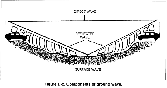
A. Ground-Wave Propagation. Ground-wave propagation involves the transmission of a radio signal along or near the surface of the earth. The ground-wave signal is divided into three parts: the direct wave, the reflected wave, and the surface wave (Figure D-2).

(1) The direct wave travels from one antenna to the other in what is called the line-of-sight mode. Maximum line-of-sight distance depends on the height of an antenna above the ground; the higher the antenna, the further the maximum line-of-sight distance. Because the radio signal travels in the air, any obstruction (such as a mountain) between the antennas can block or reduce the signal. For an antenna 10 feet above the ground, 8 kilometers (5 miles) is the maximum line-of-sight distance.
(2) The reflected wave reflects off the earth in going from the transmitting antenna to the receiving antenna. Together, the reflected wave and the direct wave are called the space wave.
(3) The surface wave travels along the surface of the earth. It is the usual means of ground-wave communication. The surface wave depends on the type of surface between the two antennas. With a good conducting surface, such as seawater, long ground-wave distances are possible. If there is a poor surface between the antennas, such as sand or frozen ground, the expected distance for the surface wave is short. The surface-wave range can also be reduced by heavy vegetation or mountainous terrain.
B. Sky-Wave Propagation. Beyond the range covered by the ground-wave signal, HF communications are possible through sky-wave propagation. Skywave propagation is possible because of the bending (refraction) of the radio signal by a region of the atmosphere called the ionosphere.
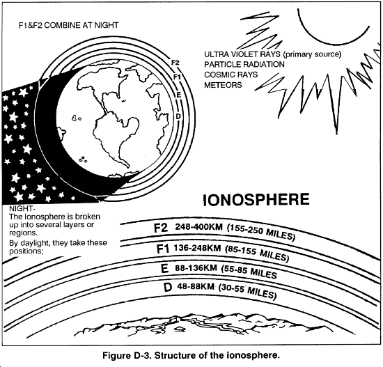
(1) The ionosphere (Figure D-3) is an electrically charged (ionized) region of the atmosphere that extends from about 60 kilometers (37 miles) to 1,000 kilometers (620 miles) above the earth's surface. The ionization results from energy from the sun and causes radio signals to return to earth. Although the ionosphere exists up to 1,000 kilometers, the important area for HF communication is below 500 kilometers. This area is divided into four regions: D, E, Fl, and F2.

(a) The majority of HF sky-wave communications depend on the F1 and F2 regions, with the F2 region being used the most for long-range daytime communications.
(b) The E region is the next lower region. It is present 24 hours a day, although at night it is much weaker. The E region is the first region with enough charge to bend radio signals. At times, parts of the E region become highly charged and can either help or block out HF communication. These highly charged areas are called sporadic E. They occur most often during the summer.
(c) The D region is closest to earth and only exists during the day. It cannot bend a radio signal back to earth, but it does play an important role in HF communication. The D region absorbs energy from the radio signal passing through it, thereby reducing the strength of the signals.
(2) The bending of the radio signal by the ionosphere depends on the frequency of the radio signal, the degree of ionization in the ionosphere, and the angle at which the radio signal strikes the ionosphere. At a vertical (straight up) angle, the highest frequency bent back to earth is called the critical frequency. Each region of the ionosphere (E, Fl, and F2) has a separate critical frequency. For a vertical angle, signals above the highest critical frequency pass through all ionospheric regions and on into outer space. Frequencies below the critical frequency of a region are bent back to the earth by that region; however, if the frequency is too low, the signal is absorbed by the D region. To have HF sky-wave communication, a radio signal must be a high enough frequency to pass through the D region, but not so high a frequency that it passes through the reflecting region. Thus, radio operators must have current propagation charts from which to choose the most effective frequency during a given time period. To achieve an NVIS effect, the radio operator subtracts 20 percent from frequencies propagated on commercial computer propagation programs.
(3) The angle at which a radio signal strikes the ionosphere plays an important part in sky-wave communication. As mentioned, any frequency above the critical frequency passes through the reflecting region. If the radio signal having a frequency above the critical frequency is sent at an angle, the signal is bent back to earth instead of passing through the region. This can be compared to skipping stones across a pond. If a stone is thrown straight down at the water, it penetrates the surface. If a stone is thrown at an angle to the pond, the stone skips across the pond. For every circuit, there is an optimum angle above the horizon called the takeoff angle. It produces the strongest signal at the receiving station. This optimum takeoff angle is used to select the antenna for a specific circuit. By placing an antenna between 1/8 wavelength and 1/4 wavelength above ground level, the radio operator achieves an NVIS effect and reduces or eliminates any skip zone.
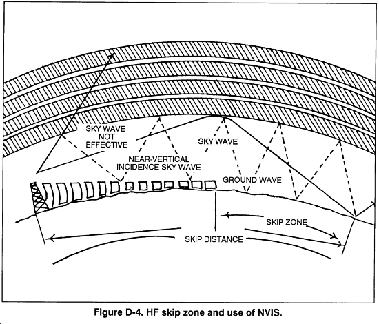
(4) Depending on the frequency, antenna, and other factors, an area may exist between the longest ground-wave range and the shortest sky-wave range where no signal exists. This is called the skip zone and no communication is possible (Figure D-4). The NVIS effect can eliminate this problem.

(5) HF propagation involves much more than what has been presented. For example, multiple frequencies are usually needed to maintain sky-wave communication. As a minimum, two frequencies, one for day and one for night are normally required.


