Products Category
- FM Transmitter
- 0-50w 50w-1000w 2kw-10kw 10kw+
- TV Transmitter
- 0-50w 50-1kw 2kw-10kw
- FM Antenna
- TV Antenna
- Antenna Accessory
- Cable Connector Power Splitter Dummy Load
- RF Transistor
- Power Supply
- Audio Equipments
- DTV Front End Equipment
- Link System
- STL system Microwave Link system
- FM Radio
- Power Meter
- Other Products
- Special for Coronavirus
Products Tags
Fmuser Sites
- es.fmuser.net
- it.fmuser.net
- fr.fmuser.net
- de.fmuser.net
- af.fmuser.net ->Afrikaans
- sq.fmuser.net ->Albanian
- ar.fmuser.net ->Arabic
- hy.fmuser.net ->Armenian
- az.fmuser.net ->Azerbaijani
- eu.fmuser.net ->Basque
- be.fmuser.net ->Belarusian
- bg.fmuser.net ->Bulgarian
- ca.fmuser.net ->Catalan
- zh-CN.fmuser.net ->Chinese (Simplified)
- zh-TW.fmuser.net ->Chinese (Traditional)
- hr.fmuser.net ->Croatian
- cs.fmuser.net ->Czech
- da.fmuser.net ->Danish
- nl.fmuser.net ->Dutch
- et.fmuser.net ->Estonian
- tl.fmuser.net ->Filipino
- fi.fmuser.net ->Finnish
- fr.fmuser.net ->French
- gl.fmuser.net ->Galician
- ka.fmuser.net ->Georgian
- de.fmuser.net ->German
- el.fmuser.net ->Greek
- ht.fmuser.net ->Haitian Creole
- iw.fmuser.net ->Hebrew
- hi.fmuser.net ->Hindi
- hu.fmuser.net ->Hungarian
- is.fmuser.net ->Icelandic
- id.fmuser.net ->Indonesian
- ga.fmuser.net ->Irish
- it.fmuser.net ->Italian
- ja.fmuser.net ->Japanese
- ko.fmuser.net ->Korean
- lv.fmuser.net ->Latvian
- lt.fmuser.net ->Lithuanian
- mk.fmuser.net ->Macedonian
- ms.fmuser.net ->Malay
- mt.fmuser.net ->Maltese
- no.fmuser.net ->Norwegian
- fa.fmuser.net ->Persian
- pl.fmuser.net ->Polish
- pt.fmuser.net ->Portuguese
- ro.fmuser.net ->Romanian
- ru.fmuser.net ->Russian
- sr.fmuser.net ->Serbian
- sk.fmuser.net ->Slovak
- sl.fmuser.net ->Slovenian
- es.fmuser.net ->Spanish
- sw.fmuser.net ->Swahili
- sv.fmuser.net ->Swedish
- th.fmuser.net ->Thai
- tr.fmuser.net ->Turkish
- uk.fmuser.net ->Ukrainian
- ur.fmuser.net ->Urdu
- vi.fmuser.net ->Vietnamese
- cy.fmuser.net ->Welsh
- yi.fmuser.net ->Yiddish
The Radio Communication-2
3. ANTENNA THEORY AND CONSTRUCTION
To select antennas for HF radio communication, the operator needs to know the concepts. This paragraph defines several basic terms and relationships, helping the operator select the best antenna.
a. Wavelength and Frequency. In radio communication, there is a definite relationship between antenna length and frequency wavelength. This relationship is important when building antennas for a specific frequency or frequency range. The wavelength of a frequency is the distance an electromagnetic wave travels to complete one cycle. (See Figure D-5.)
b. Resonance. Antennas are classified as either resonant or non-resonant, depending on their design. Both resonant and non-resonant antennas are commonly used on tactical circuits.
(1) A resonant antenna matches the length of a frequency's wavelength. In a resonant antenna, almost all of the radio signals sent to the antenna are radiated. If a resonant antenna is used for radio communication, a separate antenna must be built for each frequency used with the radio.
(2) If the antenna is used for a frequency other than the one it matches, it is nonresonant and much of the signal is lost. A nonresonant, or broadband, antenna effectively radiates a broad range of frequencies with lower efficiency. When a nonresonant antenna is used, large losses of signal power occur. Signal energy from the antenna is reflected and causes standing waves on the antenna. A measure of these standing waves, called standing wave ratio, is used to determine if an antenna is resonant at a particular frequency. A 1-to-1 standing wave ratio is the ideal situation, but 1.1-to-1 is about the best that can be done. When building wire antennas, the length of the antenna should be adjusted until the lowest standing wave ratio is measured. A 3-to-1 standing wave ratio is acceptable (check the operator's manual for the particular radio in use to determine the maximum standing wave ratio that the radio can tolerate.) In some radios, the power output of the transmitter is automatically lowered if the standing wave ratio is too high.
c. Polarization. Polarization is the relationship of radio energy radiated by an antenna to the earth. The most common polarizations are horizontal (parallel to the earth's surface) and vertical (perpendicular to the earth's surface); however, others, such as circular and elliptical, also exist. A vertical antenna normally radiates a vertically polarized signal, and a horizontal antenna normally radiates a horizontal signal. In HF ground-wave, both the transmit and receive antennas should have the same polarization for best communication. In the case of HF ground-wave propagation, vertical polarization should be used. For HF sky-wave propagation, the polarization of the transmitter and receiving antennas does not have to be the same because of the random changing of the signal as it is bent by the ionosphere. This random changing allows the use of vertical or horizontal polarization at the transmitter or receiving antenna. For sky-wave propagation, horizontal polarization is recommended to be most effective.
d. Classification. Antennas are classified according to how radio energy is radiated: omnidirectional, bidirectional, or directional.
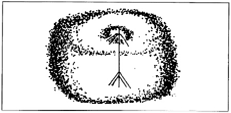
Figure D-6 Omnidirectional antenna pattern
(2) Bidirectional. A bidirectional antenna has two main lobes of radio energy opposite each other with a null between the lobes (Figure D-7). These antennas produce a stronger signal in the two opposing directions while reducing the signal in other directions. The tactical bidirectional antennas most commonly used are sloping wires, random length wires, and half-wave dipoles. Bidirectional antennas are usually used on point-to-point circuits and in situations where the antenna null can be positioned to reduce or block out interfering signals when receiving. Although bidirectional antennas are more difficult to find direction (ground-wave), they can be used when several antennas are closely located. Placement of other antennas in the null of bidirectional antennas reduces interference and interaction between the antennas. A drawback of bidirectional antennas is that they have to be correctly oriented to radiate in the desired directions. However, lowering the antenna to create the NVIS effect increases the radiation pattern allowing less accuracy in orientation of the antenna.
(3) Directional. A directional antenna has a single large lobe of radio energy in one direction (Figure D-8). It is much like a bidirectional antenna with one of its lobes cut off. Several bidirectional antennas (long-wire, sloping-Vee) are made directional by adding a terminating resistor that absorbs the second main lobe. A terminating resistor matches the antenna. A terminating resistor must be able to absorb one-half the power output of the connected transmitter and provide 400 to 600 ohms of resistance. A directional antenna concentrates almost all the radio signal in one specific direction; therefore, it must be carefully oriented. Depending on the antenna design, the main lobe of a directional antenna can cover 60 degrees or more or be a narrow pencil beam. Directional antennas are used on long-range point-to-point circuits where the concentrated radio energy is needed for circuit reliability. Directional antennas are difficult for the enemy to find the direction of transmission.
e. Antenna Construction and Selection. Antenna construction is limited only by imagination. There are many types and configurations. However, the operator must be careful not to construct an antenna that has a high standing wave ratio, which can damage radio equipment. Standing wave ratio meters should be used when testing or using unfamiliar antennas. In selecting an antenna for an HF circuit, the operator must know the type of propagation.
(1) Ground-wave propagation requires low takeoff angles and vertically polarized antennas. The whip antenna provides good omnidirectional ground-wave radiation. If a directional antenna is needed, the operator selects one with a good low-angle vertical radiation.
(2) Sky-wave propagation makes the selection of an antenna more complex. The first step is to find the distance between radio stations so that the required takeoff angle can be determined. The takeoff angle versus the distance tables gives approximate takeoff angles for day and night sky-wave propagation. If the circuit distance is 966 kilometers (600 miles) during the day, the required takeoff angle is about 25 degrees. At night, it is 40 degrees. Therefore, the operator selects an antenna that has high gain from 25 to 40 degrees. This step can be omitted if the propagation predictions give the required takeoff angles. By subtracting 20 percent from these predictions for use with NVIS constructed antennas, the operator uses a planning range of 0 to 300 miles for short-range HF communication.
(3) The radio operator decides what type of coverage is required. If the radio circuit consists of mobile (vehicular) stations or many stations at different directions from the transmitter, an omnidirectional antenna is required. If the circuit is point to point, a bidirectional or a directional antenna can be used. Normally, the receiving station locations dictate this choice.
(4) Before an antenna can be selected, the operator examines the materials available for antenna construction. If a horizontal dipole is to be erected, at least two supports are needed. (A third support in the middle is required for frequencies of 5 MHz or less.) If these supports are not available and there are no other items that can be used as supports, the dipole cannot be used. The operator checks the site of the antenna to determine if the proposed antenna will fit.
(5) Another consideration is the site itself. More times than not, the tactical situation determines the position of the communication antennas. The ideal setting is a clear flat area with no trees, buildings, fences, power lines, or mountains. Unfortunately, such an ideal location is seldom available for the tactical communicator. In choosing an antenna site, the radio operator selects an area as flat and as clear as possible. In many situations, an antenna must be put up in less ideal sites. This does not mean that the antenna will not work, but that the site affects the pattern and functioning of the antenna.
f. Half-Wave Dipole Antenna. The half-wave dipole is a balanced resonant antenna (Figure D-9). It produces its maximum gain for a narrow range of frequencies, normally 2 percent above and below the design frequency. Since frequency assignments are normally several megahertz apart, the operator must build a separate dipole for each assigned frequency. The length of a half-wave dipole is calculated from using the following formula:

The height of a dipole is normally kept at 1/4 wavelength to 1/2 wavelength above ground level for long-range sky-wave. For NVIS (O to 300 miles), the antenna should be erected between 1/8 wavelength and 1/4 wavelength above ground level. This rule also applies to the inverted Vee and sloping Vee antennas.
g. Inverted Vee. The inverted Vee, or drooping dipole, is similar to a dipole but uses only a single center support. Like a dipole, it is used for a specific frequency and has a bandwidth of plus or minus 2 percent of design frequency. Because of the inclined sides, the inverted Vee antenna produces a combination of horizontal and vertical radiation; vertical off the ends and horizontal broadside to the antenna. All the construction factors for a dipole also apply for the inverted Vee. The inverted Vee has less gain than a dipole, but the use of only a single support could make this the preferred antenna in some tactical situations. (See Figure D-10).
h. Long-Wire Antenna. A long-wire antenna is one that is long compared to a wavelength. A minimum length is 1/2 wavelength; however, antennas that are at least several wavelengths long are needed to obtain good gain and directional characteristics. The construction of long-wire antennas is simple and straight forward. The dimensions or adjustments are critical. Along-tire antenna accepts power and radiates it well on any frequency for which its overall length is not less than 1/2 wavelength (Figure D-11).
(1) Along-wire antenna is made directional by placing a terminating resistor at the distant station end of the antenna. The terminating resistor should be a 600-ohm noninductive resistor capable of absorbing at least one-half of the transmitter power. Terminating resistors are part of some radio sets. They can also be locally made, using supply system parts (National Stock Number 5905-00-764-5573, 100-watt, 106-ohm resistor).
(2) Building a long-wire antenna only requires wire, support poles, insulators, and a terminating resistor (if directionality is desired). The only requirement is that the antenna be strung in as straight a line as the situation permits. The height of the antenna is only 15 to 20 feet above ground so that tall support structures are not required.