
Products Category
- FM Transmitter
- 0-50w 50w-1000w 2kw-10kw 10kw+
- TV Transmitter
- 0-50w 50-1kw 2kw-10kw
- FM Antenna
- TV Antenna
- Antenna Accessory
- Cable Connector Power Splitter Dummy Load
- RF Transistor
- Power Supply
- Audio Equipments
- DTV Front End Equipment
- Link System
- STL system Microwave Link system
- FM Radio
- Power Meter
- Other Products
- Special for Coronavirus
Products Tags
Fmuser Sites
- es.fmuser.net
- it.fmuser.net
- fr.fmuser.net
- de.fmuser.net
- af.fmuser.net ->Afrikaans
- sq.fmuser.net ->Albanian
- ar.fmuser.net ->Arabic
- hy.fmuser.net ->Armenian
- az.fmuser.net ->Azerbaijani
- eu.fmuser.net ->Basque
- be.fmuser.net ->Belarusian
- bg.fmuser.net ->Bulgarian
- ca.fmuser.net ->Catalan
- zh-CN.fmuser.net ->Chinese (Simplified)
- zh-TW.fmuser.net ->Chinese (Traditional)
- hr.fmuser.net ->Croatian
- cs.fmuser.net ->Czech
- da.fmuser.net ->Danish
- nl.fmuser.net ->Dutch
- et.fmuser.net ->Estonian
- tl.fmuser.net ->Filipino
- fi.fmuser.net ->Finnish
- fr.fmuser.net ->French
- gl.fmuser.net ->Galician
- ka.fmuser.net ->Georgian
- de.fmuser.net ->German
- el.fmuser.net ->Greek
- ht.fmuser.net ->Haitian Creole
- iw.fmuser.net ->Hebrew
- hi.fmuser.net ->Hindi
- hu.fmuser.net ->Hungarian
- is.fmuser.net ->Icelandic
- id.fmuser.net ->Indonesian
- ga.fmuser.net ->Irish
- it.fmuser.net ->Italian
- ja.fmuser.net ->Japanese
- ko.fmuser.net ->Korean
- lv.fmuser.net ->Latvian
- lt.fmuser.net ->Lithuanian
- mk.fmuser.net ->Macedonian
- ms.fmuser.net ->Malay
- mt.fmuser.net ->Maltese
- no.fmuser.net ->Norwegian
- fa.fmuser.net ->Persian
- pl.fmuser.net ->Polish
- pt.fmuser.net ->Portuguese
- ro.fmuser.net ->Romanian
- ru.fmuser.net ->Russian
- sr.fmuser.net ->Serbian
- sk.fmuser.net ->Slovak
- sl.fmuser.net ->Slovenian
- es.fmuser.net ->Spanish
- sw.fmuser.net ->Swahili
- sv.fmuser.net ->Swedish
- th.fmuser.net ->Thai
- tr.fmuser.net ->Turkish
- uk.fmuser.net ->Ukrainian
- ur.fmuser.net ->Urdu
- vi.fmuser.net ->Vietnamese
- cy.fmuser.net ->Welsh
- yi.fmuser.net ->Yiddish
Do You Know the Basics of Power Amplifiers?
With so much attention on IBOC, it is appropriate to step back and review the basic principles of RF amplifiers.
The radio transmitter is a collection of stages. Each stage modifies the signal in some way to produce the desired output. In the first stage, an oscillator or exciter generates the desired operating frequency. The output from this section is then raised to the specified transmitter output value. This power increase may be by means of successively larger amplifying stages or in some cases, where the exciter output is sufficient, directly to the final power amplifier (PA) of the transmitter.
The RF signal transmitted must carry some information. In broadcasting, the information transmitted takes the form of speech or music and is called modulation. With amplitude modulation (AM), the RF carrier is varied in strength (amplitude) at a rate depending on the frequency of the sound.
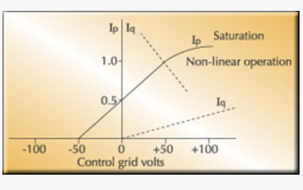
Figure 1. In a Class A amplifier, no grid current flows until the grid goes positive. Nonlinear operation occurs when the grid current stops tracking the plate current.
Regardless of where modulation of the carrier takes place, it is essential that the amplifying stage produces a clean, linearly amplified signal.
From the beginning
The earliest transmitters used amplitude modulation and this has continued in one form or another for about 100 years. It is probably the simplest method of modulation, requiring only the ability to vary the power output of an RF stage by varying the input audio signal.
In the 1930s frequency modulation (FM) was developed. It is accomplished by varying the frequency of the transmitted RF signal instead of the amplitude. Various methods of producing frequency modulation have been developed, including common mechanical and phase changing systems. Phase modulation produces the same effect in an FM receiver as frequency modulation.
The final stage of the transmitter may be directly modulated (in AM), or it receives an already modulated RF signal (FM). Many modern broadcast transmitters use solid-state modules in their power amplifier stages, however, there are still a considerable number of transmitters that continue to use vacuum tubes in their final stages. Solid-state devices provide considerable reduction in operating costs and their use provides the ability, in most cases, to change a faulty module on an operating transmitter without having to shut down.
Know the A, B, Cs
The most important characteristic of an amplifier is linearity. That is the ability of the stage to amplify all parts by the same amount so that all signals are amplified equally.
In a class A amplifier, current flows constantly and is not cut off during any part of the cycle. In a tube design, this is achieved by supplying sufficient negative bias voltage to the control grid to ensure that it never goes positive above 0V at any time in the cycle.
This means that no grid current flows and the source is not required to produce any drive power. For example, if the input signal has a 30V swing and the bias is -30V, the grid voltage would swing between -60V and 0V and no plate current would flow.
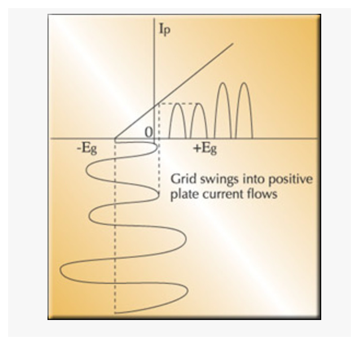
Figure 2. When a Class B amplifier is heavily cutoff, the positive peaks cause grid current and plate current flow in a series of half-wave pulses.
Because class A amplifiers are inherently inefficient in terms of required voltage and current, they are not generally used today in commercial broadcast transmitters. Instead, class B and class C amplifiers are common or variations of class B and class C circuits, such as a class AB amplifier.
With the introduction of pulse-duration modulation and digital operation systems, amplifiers have changed considerably, but the basic facts still apply.
The principles of amplification remain the same regardless of whether it is a tube or a solid-state amplifier. Because of the proliferation of high-power transmitters still using tubes, consider the control characteristics of a vacuum tube amplifier.
Figure 1 shows the dynamic characteristics of a triode tube amplifier. The solid line represents the plate current. The intersection of this line and the negative grid voltage axis shows the cut-off point at which the tube is so heavily negatively biased that no plate current flows. As the negative bias is decreased and passes through zero into the positive region, the plate current increases. The more steeply the plate current rises as the grid voltage becomes positive, the greater the transconductance of the tube. This controls the amplification factor. As the superimposed RF voltage is applied to the control grid, the bias becomes more negative on negative peaks and less negative on positive peaks. However the grid will never become positive so that no grid current will flow.
Differences in options
In class B operation, the control grid bias is increased so that the plate current is just at cut-off. The positive portion of the applied signal will cause plate current to flow immediately. No matter how far negative the grid goes, plate current will never flow. This type of operation requires sufficient signal voltage to drive the grid positive. The peak plate current is raised and sometimes the average plate current uses two tubes in push-pull operation. Figure 2 shows the operating characteristics. The output is a series of half waves with an efficiency of about 65 percent.
Class C operation is similar except that the control grid is biased far past cut off. Plate current only flows with high excitation and can reach saturation. Efficiency is high, around 90 percent. However, the waveform can be badly distorted in class B and C operation. Because of this, the correct load impedance must contain a resistive component to develop the required power. This is usually the input resistance of the transmission line.
If you are interested in Power Amplifier and FM/TV Transmitter Equipment, please feel free to contact us:[email protected] .
