
Products Category
- FM Transmitter
- 0-50w 50w-1000w 2kw-10kw 10kw+
- TV Transmitter
- 0-50w 50-1kw 2kw-10kw
- FM Antenna
- TV Antenna
- Antenna Accessory
- Cable Connector Power Splitter Dummy Load
- RF Transistor
- Power Supply
- Audio Equipments
- DTV Front End Equipment
- Link System
- STL system Microwave Link system
- FM Radio
- Power Meter
- Other Products
- Special for Coronavirus
Products Tags
Fmuser Sites
- es.fmuser.net
- it.fmuser.net
- fr.fmuser.net
- de.fmuser.net
- af.fmuser.net ->Afrikaans
- sq.fmuser.net ->Albanian
- ar.fmuser.net ->Arabic
- hy.fmuser.net ->Armenian
- az.fmuser.net ->Azerbaijani
- eu.fmuser.net ->Basque
- be.fmuser.net ->Belarusian
- bg.fmuser.net ->Bulgarian
- ca.fmuser.net ->Catalan
- zh-CN.fmuser.net ->Chinese (Simplified)
- zh-TW.fmuser.net ->Chinese (Traditional)
- hr.fmuser.net ->Croatian
- cs.fmuser.net ->Czech
- da.fmuser.net ->Danish
- nl.fmuser.net ->Dutch
- et.fmuser.net ->Estonian
- tl.fmuser.net ->Filipino
- fi.fmuser.net ->Finnish
- fr.fmuser.net ->French
- gl.fmuser.net ->Galician
- ka.fmuser.net ->Georgian
- de.fmuser.net ->German
- el.fmuser.net ->Greek
- ht.fmuser.net ->Haitian Creole
- iw.fmuser.net ->Hebrew
- hi.fmuser.net ->Hindi
- hu.fmuser.net ->Hungarian
- is.fmuser.net ->Icelandic
- id.fmuser.net ->Indonesian
- ga.fmuser.net ->Irish
- it.fmuser.net ->Italian
- ja.fmuser.net ->Japanese
- ko.fmuser.net ->Korean
- lv.fmuser.net ->Latvian
- lt.fmuser.net ->Lithuanian
- mk.fmuser.net ->Macedonian
- ms.fmuser.net ->Malay
- mt.fmuser.net ->Maltese
- no.fmuser.net ->Norwegian
- fa.fmuser.net ->Persian
- pl.fmuser.net ->Polish
- pt.fmuser.net ->Portuguese
- ro.fmuser.net ->Romanian
- ru.fmuser.net ->Russian
- sr.fmuser.net ->Serbian
- sk.fmuser.net ->Slovak
- sl.fmuser.net ->Slovenian
- es.fmuser.net ->Spanish
- sw.fmuser.net ->Swahili
- sv.fmuser.net ->Swedish
- th.fmuser.net ->Thai
- tr.fmuser.net ->Turkish
- uk.fmuser.net ->Ukrainian
- ur.fmuser.net ->Urdu
- vi.fmuser.net ->Vietnamese
- cy.fmuser.net ->Welsh
- yi.fmuser.net ->Yiddish
An Inductive Transducer : Working & Its Applications
A device that can convert one form of energy into another form is called a transducer. That means a transducer has the ability to convert a signal of one form to another form. These are mainly used for automation, measurement, and control systems because the electrical signal needs to be converted to physical quantities like force, torque, motion, etc. An electric motor, solar cell, incandescent bulb, microphone, etc are examples of transducers. A transducer can be electrical or mechanical. An electrical transducer can convert physical energy into electrical energy. A mechanical transducer can convert electrical energy into mechanical energy. This article describes an inductive transducer, which is an electrical transducer.What is an Inductive Transducer?Definition: A transducer that works on the principle of electromagnetic induction or transduction mechanism is called an inductive transducer. A self-inductance or mutual inductance is varied to measure required physical quantities like displacement (rotary or linear), force, pressure, velocity, torque, acceleration, etc. These physical quantities are noted as measurands. Linear Variable Differential Transducer (LVDT) is an example of an inductive transducer. Using LVDT, displacement is measured in terms of the voltage induced in the winding by moving the core in one direction. Types of the Inductive TransducerInductive transducers may be of passive-type or self-generating type. The tachometer is the example of a self-generating inductive transducer. LVDT is an example of a passive type inductive transducer. Inductive transducers are divided into two types. They are,Simple Inductance TypeIn this type of transducer, a single coil is used to measure the required parameter. The change in displacement changes the permeability of the flux produced in the circuit results in a change in the inductance of the coil and the output. The output can be calibrated in terms of the measurand, which is to be measured. The circuit of a simple inductance type is shown below. Single inductance type is again divided into two types.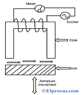 Simple Inductance Type Single Coil Inductance TypeWhen the armature of the circuit is moved, the air gap between the magnetic materials and the permeability of the flux produced in the circuit changes. This results in a change of the inductance in the circuit. This type is used mainly in counting the no.of objects. The circuit of a single-coil inductance type is shown below.Hallow Coil Inductive Type CircuitThe magnetic core can be moved inside the hallow material, which has a coil wound around the hallow magnetic material The output is proportional to the input and it can be calibrated in terms of the measurand. The air gap decides the change in the magnetic field of the coils and the flux linkage.Mutual Inductance Transducers (two coils)In this type, two coils are used for mutual induction. One for generating excitation and another for output. The voltage difference between the two coils depends on the movement of the armature. When the armature position is changed by connecting to the movable mechanical element, then the inductance changes. The air gap between the armature and the magnetic material and also voltage induced in the coil depends on the change in the armature position. This type is also called a differential mutual inductive transducer.
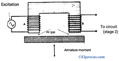 Mutual Inductance Transducer Inductive Transducer Working PrincipleGenerally, inductive transducers works on the principle of change in self-inductance of one coil, change in mutual inductance of two-coils and eddy current production. The voltage difference and change in inductance results due to the change in flux in the coils (secondary or primary coils). The working principle of the inductive transducer is explained below.Change in Self-inductanceConsider the self-inductance of the coil be,L = N2/RThe expression for the reluctance of the coil is, R = l/µAL = N2µA/lL = N2µGWhere ‘N’ represents no.of turns‘R’ represents the magnetic circuit’s reluctance‘μ’ represents permeability of the coil (medium in and around the coil)G= A/l = geometric form factor‘A’ represents a cross-section area of the coil‘l’ represents the length of the coilFrom the above equations, we can observe that self-inductance can be varied or changed by changing the no.of turns, or geometric form factor or permeability of the coil.The displacement can be measured directly in terms of inductance by changing any of the above parameters (turns, form factor, permeability). We can also calibrate the instrument against measurand.Change in Mutual InductanceInductive transducers also on the principle of mutual inductance of multiple coils.We consider the two coils, which have self-inductance L1 and L2The mutual inductance of the coils is given by,M = K √L1L2Where ‘K’ represents the coefficient of coupling.Hence, the mutual inductance can be changed by varying the self-inductance of the individual coils or by changing the coefficient of coupling. The factor K depends on the distance and orientation of the coils.To measure the displacement, one coil is fixed and the other coil is connected to a movable object. As the object moves, the factor K changes, which results in a change in mutual inductance in the coils. This change can be calibrated in terms of displacement for an instrument.Eddy Current ProductionThe production of eddy current in the inductive transducer can be varied by changing the conductive plate placed near the coil. When the conductive plate is placed near the coil that carries alternating current, eddy currents are induced in the plate which has its own magnetic field acts against the coil. The conductive plate that carries circulating current is called eddy current.When the conductive plate is brought near to the coil, then the eddy current is produced with its own magnetic flux, which reduces the magnetic flux of the coil and inductance. As the distance between the coil and the conductive plate is decreased, higher eddy currents are produced and more reduction in the inductance of the coil and vice versa. Hence the change in inductance can be measured by moving the conductive plate. This Change can be calibrated to measure the physical quantity called displacement in an instrument.Advantages/Disadvantages of Inductive TransducerThe advantages of the inductive transducer include the following.The inductive transducers can work in any environmental conditions like humidity and high temperatures. These can give high performance in the industrial environment also.These have high accuracy and stable operating range with good life-spanThese can be operated in high switching rates in industrial applications.These type transducers can be operated in wide ranges used in various applicationsThe disadvantages of the inductive transducer include the following.The working and operating range of inductive transducer depends on the construction and temperature conditionsIt depends on the magnetic field of the coil.Applications of the Inductive TransducerInductive transducers are used in,Proximity sensors to measure position, dynamic motion, touchpads, etc.Detection of metals and missing partsCounting the no.of objects.AccelerometersLinear and Rotary MotorGalvanometersLVDT and RVDTPressure and airflow sensorsElectroactive polymersPotential metersMicro-electro-mechanical systemsPowered generators etc.Sequential countersPB monitors, heart monitors, etcThus, this is all about an overview of the inductive transducer – definition, types, working principle, applications, advantages, and disadvantages. Here is a question for you, ” What is the operating range of inductive transducer?”
Also Read:
What is Resistive Transducer – Working & Its Applications
