
Products Category
- FM Transmitter
- 0-50w 50w-1000w 2kw-10kw 10kw+
- TV Transmitter
- 0-50w 50-1kw 2kw-10kw
- FM Antenna
- TV Antenna
- Antenna Accessory
- Cable Connector Power Splitter Dummy Load
- RF Transistor
- Power Supply
- Audio Equipments
- DTV Front End Equipment
- Link System
- STL system Microwave Link system
- FM Radio
- Power Meter
- Other Products
- Special for Coronavirus
Products Tags
Fmuser Sites
- es.fmuser.net
- it.fmuser.net
- fr.fmuser.net
- de.fmuser.net
- af.fmuser.net ->Afrikaans
- sq.fmuser.net ->Albanian
- ar.fmuser.net ->Arabic
- hy.fmuser.net ->Armenian
- az.fmuser.net ->Azerbaijani
- eu.fmuser.net ->Basque
- be.fmuser.net ->Belarusian
- bg.fmuser.net ->Bulgarian
- ca.fmuser.net ->Catalan
- zh-CN.fmuser.net ->Chinese (Simplified)
- zh-TW.fmuser.net ->Chinese (Traditional)
- hr.fmuser.net ->Croatian
- cs.fmuser.net ->Czech
- da.fmuser.net ->Danish
- nl.fmuser.net ->Dutch
- et.fmuser.net ->Estonian
- tl.fmuser.net ->Filipino
- fi.fmuser.net ->Finnish
- fr.fmuser.net ->French
- gl.fmuser.net ->Galician
- ka.fmuser.net ->Georgian
- de.fmuser.net ->German
- el.fmuser.net ->Greek
- ht.fmuser.net ->Haitian Creole
- iw.fmuser.net ->Hebrew
- hi.fmuser.net ->Hindi
- hu.fmuser.net ->Hungarian
- is.fmuser.net ->Icelandic
- id.fmuser.net ->Indonesian
- ga.fmuser.net ->Irish
- it.fmuser.net ->Italian
- ja.fmuser.net ->Japanese
- ko.fmuser.net ->Korean
- lv.fmuser.net ->Latvian
- lt.fmuser.net ->Lithuanian
- mk.fmuser.net ->Macedonian
- ms.fmuser.net ->Malay
- mt.fmuser.net ->Maltese
- no.fmuser.net ->Norwegian
- fa.fmuser.net ->Persian
- pl.fmuser.net ->Polish
- pt.fmuser.net ->Portuguese
- ro.fmuser.net ->Romanian
- ru.fmuser.net ->Russian
- sr.fmuser.net ->Serbian
- sk.fmuser.net ->Slovak
- sl.fmuser.net ->Slovenian
- es.fmuser.net ->Spanish
- sw.fmuser.net ->Swahili
- sv.fmuser.net ->Swedish
- th.fmuser.net ->Thai
- tr.fmuser.net ->Turkish
- uk.fmuser.net ->Ukrainian
- ur.fmuser.net ->Urdu
- vi.fmuser.net ->Vietnamese
- cy.fmuser.net ->Welsh
- yi.fmuser.net ->Yiddish
RF directional coupler basics tutorial
Date:2014/3/26 10:56:32 Hits:
RF directional coupler basics tutorial
- overview, information and tutorial about the basics of the directional coupler and basic directional coupler designRF directional couplers are often used in RF design applications. Directional couplers are RF passive devices used to couple a specific proportion of the power travelling in one transmission line out through another connection or port. Directional couplers find many applications in RF design , ranging from through line power sensors to transmitter automatic levels controls. As such they are particularly useful, enabling power levels to be sensed without making a direct connection to the transmission line carrying the power.
RF directional couplers can be implemented using a variety of techniques including stripline, coaxial feeder and lumped or discrete elements. They may also be contained within a variety of packages from blocks with RF connectors, or solder pins, or they may be contained on a substrate carrier, or they may be constructed as part of a larger unit containing other functions.
RF directional coupler basics
An RF directional coupler is a four port device. The four ports are generally termed:
-Input (Port 1, Incident)-Transmitted (Port 2, Output)
-Coupled (Port 3, Forward coupled port)
-Isolated (Port 4, Reverse coupled port)
Terms in brackets refer to alternative names for the ports that may be seen on occasions.
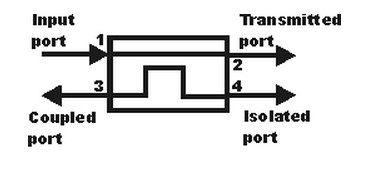
RF Directional Coupler
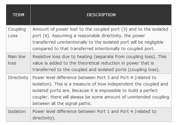
RF directional coupler specifications
As with any component or system, there are several specifications associated with RF directional couplers. The major RF directional coupler specifications are summarised in the table below.
RF directional coupler practical considerations
there are a number of physical considerations that need to be taken into account when choosing and using RF directional couplers.
Leave a message
Message List
Comments Loading...
