
Products Category
- FM Transmitter
- 0-50w 50w-1000w 2kw-10kw 10kw+
- TV Transmitter
- 0-50w 50-1kw 2kw-10kw
- FM Antenna
- TV Antenna
- Antenna Accessory
- Cable Connector Power Splitter Dummy Load
- RF Transistor
- Power Supply
- Audio Equipments
- DTV Front End Equipment
- Link System
- STL system Microwave Link system
- FM Radio
- Power Meter
- Other Products
- Special for Coronavirus
Products Tags
Fmuser Sites
- es.fmuser.net
- it.fmuser.net
- fr.fmuser.net
- de.fmuser.net
- af.fmuser.net ->Afrikaans
- sq.fmuser.net ->Albanian
- ar.fmuser.net ->Arabic
- hy.fmuser.net ->Armenian
- az.fmuser.net ->Azerbaijani
- eu.fmuser.net ->Basque
- be.fmuser.net ->Belarusian
- bg.fmuser.net ->Bulgarian
- ca.fmuser.net ->Catalan
- zh-CN.fmuser.net ->Chinese (Simplified)
- zh-TW.fmuser.net ->Chinese (Traditional)
- hr.fmuser.net ->Croatian
- cs.fmuser.net ->Czech
- da.fmuser.net ->Danish
- nl.fmuser.net ->Dutch
- et.fmuser.net ->Estonian
- tl.fmuser.net ->Filipino
- fi.fmuser.net ->Finnish
- fr.fmuser.net ->French
- gl.fmuser.net ->Galician
- ka.fmuser.net ->Georgian
- de.fmuser.net ->German
- el.fmuser.net ->Greek
- ht.fmuser.net ->Haitian Creole
- iw.fmuser.net ->Hebrew
- hi.fmuser.net ->Hindi
- hu.fmuser.net ->Hungarian
- is.fmuser.net ->Icelandic
- id.fmuser.net ->Indonesian
- ga.fmuser.net ->Irish
- it.fmuser.net ->Italian
- ja.fmuser.net ->Japanese
- ko.fmuser.net ->Korean
- lv.fmuser.net ->Latvian
- lt.fmuser.net ->Lithuanian
- mk.fmuser.net ->Macedonian
- ms.fmuser.net ->Malay
- mt.fmuser.net ->Maltese
- no.fmuser.net ->Norwegian
- fa.fmuser.net ->Persian
- pl.fmuser.net ->Polish
- pt.fmuser.net ->Portuguese
- ro.fmuser.net ->Romanian
- ru.fmuser.net ->Russian
- sr.fmuser.net ->Serbian
- sk.fmuser.net ->Slovak
- sl.fmuser.net ->Slovenian
- es.fmuser.net ->Spanish
- sw.fmuser.net ->Swahili
- sv.fmuser.net ->Swedish
- th.fmuser.net ->Thai
- tr.fmuser.net ->Turkish
- uk.fmuser.net ->Ukrainian
- ur.fmuser.net ->Urdu
- vi.fmuser.net ->Vietnamese
- cy.fmuser.net ->Welsh
- yi.fmuser.net ->Yiddish
RF combiner, splitter / divider basics
Date:2014/3/27 15:32:57 Hits:
RF combiner, splitter / divider basics
- overview and introduction to the basic concepts of RF combiners and RF splittersRF combiners and splitters are widely used in RF applications. The enable RF power to be split or combined within an environment where the characteristic impedance is maintained.
RF power combiners and RF splitters are the same items. The same circuits can be used to combine and split RF power, the only difference being that RF power is applied to one port and extracted from other in the case of the RF splitter, and for the RF combiner, power is applied in the opposite direction.
Types of RF splitter combiners
There are two broad categories of RF splitters:
-Resistive power splitters: As the name implies, these power splitters and combiners use resistors. While they are able to maintain the characteristic impedance of the system, the use of resistors introduces loss above that of the minimum caused any splitting action. They are cheap and easy to make.-Hybrid power splitters: Hybrid splitters use transformers and are able to provide low levels of loss. Although there are some physical losses in the transformer, the major "loss" is that arising from the splitting process as the same signal is shared between a number of outputs.
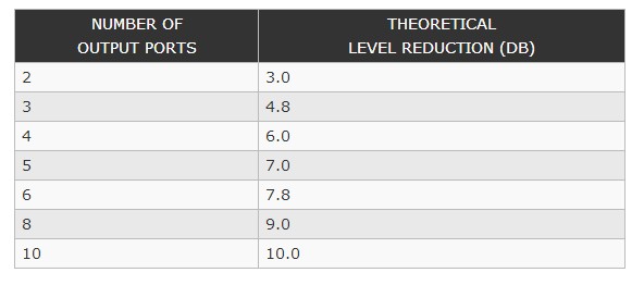
Power splitter insertion loss
When a splitter is inserted into a circuit, there are naturally some losses resulting from the fact that no component is perfectly lossless. These losses are generally minimised and cannot be calculated exactly.
This power reduction can be calculated and table of the levels for power splitters with different numbers of outputs is given below.
Leave a message
Message List
Comments Loading...
