
Products Category
- FM Transmitter
- 0-50w 50w-1000w 2kw-10kw 10kw+
- TV Transmitter
- 0-50w 50-1kw 2kw-10kw
- FM Antenna
- TV Antenna
- Antenna Accessory
- Cable Connector Power Splitter Dummy Load
- RF Transistor
- Power Supply
- Audio Equipments
- DTV Front End Equipment
- Link System
- STL system Microwave Link system
- FM Radio
- Power Meter
- Other Products
- Special for Coronavirus
Products Tags
Fmuser Sites
- es.fmuser.net
- it.fmuser.net
- fr.fmuser.net
- de.fmuser.net
- af.fmuser.net ->Afrikaans
- sq.fmuser.net ->Albanian
- ar.fmuser.net ->Arabic
- hy.fmuser.net ->Armenian
- az.fmuser.net ->Azerbaijani
- eu.fmuser.net ->Basque
- be.fmuser.net ->Belarusian
- bg.fmuser.net ->Bulgarian
- ca.fmuser.net ->Catalan
- zh-CN.fmuser.net ->Chinese (Simplified)
- zh-TW.fmuser.net ->Chinese (Traditional)
- hr.fmuser.net ->Croatian
- cs.fmuser.net ->Czech
- da.fmuser.net ->Danish
- nl.fmuser.net ->Dutch
- et.fmuser.net ->Estonian
- tl.fmuser.net ->Filipino
- fi.fmuser.net ->Finnish
- fr.fmuser.net ->French
- gl.fmuser.net ->Galician
- ka.fmuser.net ->Georgian
- de.fmuser.net ->German
- el.fmuser.net ->Greek
- ht.fmuser.net ->Haitian Creole
- iw.fmuser.net ->Hebrew
- hi.fmuser.net ->Hindi
- hu.fmuser.net ->Hungarian
- is.fmuser.net ->Icelandic
- id.fmuser.net ->Indonesian
- ga.fmuser.net ->Irish
- it.fmuser.net ->Italian
- ja.fmuser.net ->Japanese
- ko.fmuser.net ->Korean
- lv.fmuser.net ->Latvian
- lt.fmuser.net ->Lithuanian
- mk.fmuser.net ->Macedonian
- ms.fmuser.net ->Malay
- mt.fmuser.net ->Maltese
- no.fmuser.net ->Norwegian
- fa.fmuser.net ->Persian
- pl.fmuser.net ->Polish
- pt.fmuser.net ->Portuguese
- ro.fmuser.net ->Romanian
- ru.fmuser.net ->Russian
- sr.fmuser.net ->Serbian
- sk.fmuser.net ->Slovak
- sl.fmuser.net ->Slovenian
- es.fmuser.net ->Spanish
- sw.fmuser.net ->Swahili
- sv.fmuser.net ->Swedish
- th.fmuser.net ->Thai
- tr.fmuser.net ->Turkish
- uk.fmuser.net ->Ukrainian
- ur.fmuser.net ->Urdu
- vi.fmuser.net ->Vietnamese
- cy.fmuser.net ->Welsh
- yi.fmuser.net ->Yiddish
3 Main Types of Crowbar Circuits for Over-voltage Protection

Overvoltage is always one of the main problems in circuit protection, and the crowbar circuit is one of the main solutions for it. The crowbar circuit can cause a fuse to blow by subjecting it to a high current. What do you know about the crowbar circuit?
This share contains the definition of the crowbar circuit, how does the crowbar circuit work, and the introduction to the 3 main types of crowbar circuits that used in different applications. If you are being troubled by overvoltage, you can find a better solution for overvoltage protection and have a further understanding of the crowbar circuits. Let's keep reading!
Sharing is Caring!
Content
● How Does a Crowbar Circuit Work?
● A Crowbar Using Triac and SSB
● A Crowbar Circuit Using Triac and Zener Diode
● A Fuse Crowbar Circuit with a Simple SCR
● FAQ
A very simple DC over voltage protector circuit is shown below. The transistor is set to monitor the input voltage applied to it from the left, in case the voltage rises above a specified limit, the transistor conducts, providing the required current to the SCR, which instantly fires, shorting the output and thus protecting the load from the hazard. It's also called a Crowbar circuit.
How Does a Crowbar Circuit Work?
The circuit shown below is very simple to understand and is quite self explanatory. The working may be understood with the following points:
● The supply DC input voltage is applied from the right hand side o the circuit across the SCR.
● As long as the input voltage remains under a certain predetermined value, the transistor is unable to conduct and therefore the SCr also remains shut.
● The threshold voltage is effectively set by zener diode voltage.
● As long as the input voltage stays below this threshold everything goes on fine.
● However in case the input crosses the above threshold level, the zener diode for setting threshold voltage starts conducting so that the base of the transistor starts getting biased.
● At some point of time the transistor becomes fully biased and pulls the positive voltage to its collector terminal.
● The voltage at the collector instantly passes through the gate of the SCR.
● The SCR immediately conducts and shorts the input to ground. This may look a bit dangerous because the situation indicates that the SCR might get damaged as it shorts the voltage directly through it.
But the SCR remains absolutely safe because the moment the input voltage drops below the set threshold the transistor stops conducting and inhibits the SCR from going into damaging extents.
The situation is sustained and keeps the voltage under control and prevents it from reaching above the threshold, in this way the circuit is able to accomplish the DC over protection function.
The introduction to Crowbar Circuit and How Does It Work
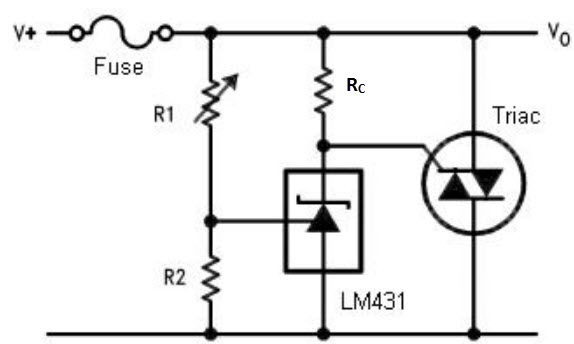
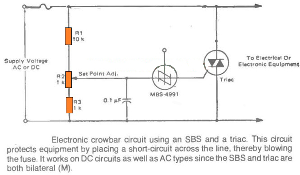
The next circuit which can protect your valuable gadget from over voltage situations is shown in the following image, which uses a SSB or a silicon bilateral switch, as the gate driver for the triac.
● The preset R2 is used for setting the triggering point of the SSB at which the device can fire and trigger ON the triac. This setting is done corresponding to the desired high voltage level at which the crowbar needs to trigger and protect the connected circuit from a possible burn out.
● As soon as the high voltage situation is reached, as per the R2 setting the SSB detects this over voltage and it switches ON. Once it switch es ON it fires the triac. The triac instantly conducts and shorts circuits the line voltage which in turn causes the fuse to blow. Once the fuse blows, the voltage to the load is cut off and the danger of the over voltage is averted.
A silicon bilateral switch ( SBS ) is a synchronizable diac that can be used for low voltage dimmers. As soon as the voltage across the main power terminals MT1 and MT2 rises above the trigger voltage (typically 8.0 V, significantly lower than the diac), the SBS trips and continues to conduct as long as the current through it is above the holding current . The holding voltage is around 1.4 V at 200 mA. If the current becomes smaller than the holding current, the SBS will turn off again.
This operation applies to both directions, so the component is suitable for AC applications. A pulse on gate G can conduct the SBS even without the trigger voltage being reached. The operation can be compared to that of two anti-parallel thyristors with a common gate and between the nodes of anode and cathode and this gate two zener diodes of about 15 V (which start conducting at 7.5 V).
A Crowbar Circuit Using Triac and Zener Diode
If you do not get an SSB, the same crowbar application as above can be designed using a triac and a zener diodes as shown in the following diagram.
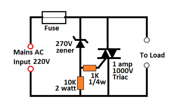
Here, the zener voltage decides the cut off limit of the crowbar circuit. In the figure it is shown as 270V, therefore as soon as the 270 V mark is reached, the zener starts conducting. As soon as the zener diode breaks over and conducts, the triac is switched ON.
The triac switches ON and short circuits the line voltage thereby bowing off the fuse the preventing further dangers that may resulted in due to the high voltage.
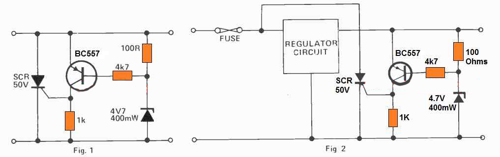
A Fuse Crowbar Circuit Using SCR
This is yet another simple SCR transistor crowbar circuit which delivers over-voltage protection in case there is a malfunction of the voltage regulator for over-voltage protection or high level from an external source. It is supposed to be employed with a supply source that includes some type of short circuit protection, possibly fold-back current limiting or a basic fuse. The best possible application can be a 5V logic supply, because TTL could be quickly destroyed by too much voltage.
The values of the parts selected in Fig.1 are with respect to a 5V supply, even though any kind of supply up to about 25V could be protected using this crowbar network, just by picking the right zener diode.
Here, the zener voltage decides the cut off limit of the crowbar circuit. In the figure it is shown as 270V, therefore as soon as the 270 V mark is reached, the zener starts conducting. As soon as the zener diode breaks over and conducts, the triac is switched ON.
The triac switches ON and short circuits the line voltage thereby bowing off the fuse the preventing further dangers that may resulted in due to the high voltage.
Any time the supply voltage is greater than the zener voltage by +0.7V, the transistor activates and triggers the SCR. When this happens it short circuits the supply, stopping the voltage from increasing any more. If it is used in a power supply which only has a fuse protection, it is advisable to attach the SCR right around the unregulated supply as indicated in Fig.2 in order to protect against damage to the regulator circuit as soon as the crowbar triggers ON.
1. Q: How Does Crowbar Protection Circuit Over Voltage Protection Work?
A: The crowbar circuit monitors the input voltage. When it exceeds the limit, it will cause a short circuit on the power line and blow the fuse. Once the fuse blows, the power supply will be disconnected from the load to prevent it from withstanding high voltage.
2. Q: What Purpose of Crowbar is a Circuit?
A: Crowbar circuit is a circuit used to prevent overvoltage or surge of the power supply unit from damaging the circuit connected to the power supply.
3. Q: What are the Types of Overvoltage?
A: The overvoltage that exerts pressure on the power system can be divided into two main types: 1-external overvoltage: these disturbances caused by atmospheric disturbances, lightning stroke is the most common and serious. 2. Internal Overvoltage: caused by changes in network operating conditions.
4. Q: What is Overvoltage Protection?
A: Overvoltage protection is a power function. When the voltage exceeds the preset level, it will turn off the power supply or clamp the output overvoltage may occur in the power supply due to internal failure of the power supply or external reasons such as distribution lines.
In this share, we learn the definition of the crowbar circuit, how does the crowbar circuit work, and have a understanding of 3 main types of crowbar circuits that used in different applications. Having a further understanding of the crowbar circuits can help you solve the overvoltage efficiently. Do you want more about the crowbar circuits? Leave your comments below and tell us your ideas. And If you think this share is helpful for you, don't forget to share it!
Also Read
● How SCR Thyristor Overvoltage Crowbar Circuits Protects Power Supplies from Overvoltage?
● How to Measure Transient Response of a Switching Regulator?
● Things You Should Not Miss About Facebook Meta and Metaverse
● How LTM8022 μModule Regulator Provides a Better Design for Power Supply?
