
Products Category
- FM Transmitter
- 0-50w 50w-1000w 2kw-10kw 10kw+
- TV Transmitter
- 0-50w 50-1kw 2kw-10kw
- FM Antenna
- TV Antenna
- Antenna Accessory
- Cable Connector Power Splitter Dummy Load
- RF Transistor
- Power Supply
- Audio Equipments
- DTV Front End Equipment
- Link System
- STL system Microwave Link system
- FM Radio
- Power Meter
- Other Products
- Special for Coronavirus
Products Tags
Fmuser Sites
- es.fmuser.net
- it.fmuser.net
- fr.fmuser.net
- de.fmuser.net
- af.fmuser.net ->Afrikaans
- sq.fmuser.net ->Albanian
- ar.fmuser.net ->Arabic
- hy.fmuser.net ->Armenian
- az.fmuser.net ->Azerbaijani
- eu.fmuser.net ->Basque
- be.fmuser.net ->Belarusian
- bg.fmuser.net ->Bulgarian
- ca.fmuser.net ->Catalan
- zh-CN.fmuser.net ->Chinese (Simplified)
- zh-TW.fmuser.net ->Chinese (Traditional)
- hr.fmuser.net ->Croatian
- cs.fmuser.net ->Czech
- da.fmuser.net ->Danish
- nl.fmuser.net ->Dutch
- et.fmuser.net ->Estonian
- tl.fmuser.net ->Filipino
- fi.fmuser.net ->Finnish
- fr.fmuser.net ->French
- gl.fmuser.net ->Galician
- ka.fmuser.net ->Georgian
- de.fmuser.net ->German
- el.fmuser.net ->Greek
- ht.fmuser.net ->Haitian Creole
- iw.fmuser.net ->Hebrew
- hi.fmuser.net ->Hindi
- hu.fmuser.net ->Hungarian
- is.fmuser.net ->Icelandic
- id.fmuser.net ->Indonesian
- ga.fmuser.net ->Irish
- it.fmuser.net ->Italian
- ja.fmuser.net ->Japanese
- ko.fmuser.net ->Korean
- lv.fmuser.net ->Latvian
- lt.fmuser.net ->Lithuanian
- mk.fmuser.net ->Macedonian
- ms.fmuser.net ->Malay
- mt.fmuser.net ->Maltese
- no.fmuser.net ->Norwegian
- fa.fmuser.net ->Persian
- pl.fmuser.net ->Polish
- pt.fmuser.net ->Portuguese
- ro.fmuser.net ->Romanian
- ru.fmuser.net ->Russian
- sr.fmuser.net ->Serbian
- sk.fmuser.net ->Slovak
- sl.fmuser.net ->Slovenian
- es.fmuser.net ->Spanish
- sw.fmuser.net ->Swahili
- sv.fmuser.net ->Swedish
- th.fmuser.net ->Thai
- tr.fmuser.net ->Turkish
- uk.fmuser.net ->Ukrainian
- ur.fmuser.net ->Urdu
- vi.fmuser.net ->Vietnamese
- cy.fmuser.net ->Welsh
- yi.fmuser.net ->Yiddish
How to Measure Transient Response of a Switching Regulator?
In order to understand the stability of a switching regulator, we often need to measure its load transient response. Therefore, learning how to measure transient response is essential for engineers in the field of electronics.
In this share, we would explain the definition of load transient response, the main key points in a measurement, how to measure transient response with FRA, and an actual example of measuring and adjusting the load transient response of a switching regulator. If you are not clear about how to measure the transient response, you can get the hang of the method through this share. Let's keep reading!
Sharing is Caring!
Content
● What is Load Transient Response?
● 5 Key Points in Evaluating Transient Response
● How to Evaluate Transient Response?
● Example of Adjusting Transient Response
● FAQ
What is Load Transient Response?
Load transient response is the response characteristic to a sudden load fluctuation, that is, the time until the output voltage returns to a preset value after having fallen or risen, and the waveform of the output voltage. It is an essential parameter because it relates to the stability of the output voltage with respect to the load current.
In contrast with load regulation, it is, just as the name implies a transient-state characteristic. Actual phenomena are explained using the following graphs.
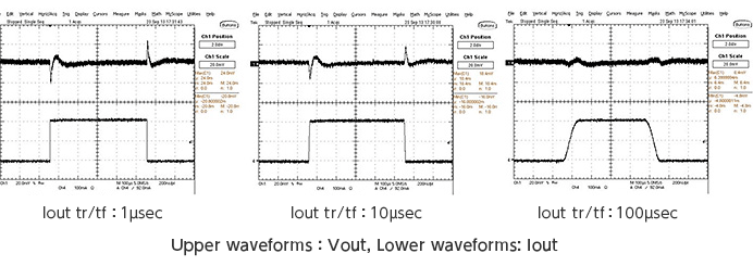
There are some points to notice about the graph:
● In the waveforms of the graph on the left, the load current (the lower waveform) rises from zero rapidly, with a rise time (tr) of 1 µsec.
● On the other hand, the output voltage (upper waveform) momentarily drops, and thereafter rises rapidly, slightly exceeding the steady-state voltage, then drops again to a stable state.
● When the load current drops suddenly, we see that the opposite reaction occurs.
To explain things in a somewhat less formal way:
● When the load increases, suddenly more current is needed, and the output current is not supplied fast enough, so the voltage drops.
● In this operation, the maximum output current is supplied for a number of cycles in order to return the dropped voltage to its preset value, but a little too much is supplied and the voltage rises a bit higher, and so the supplied current is lowered so that the preset value is reached.
This should be understood as a description of normal transient response. When there are other factors and abnormalities, other phenomena are included in addition to this.
In an ideal load transient response, there is response to a fluctuation in load current over few switching cycles (a short length of time), and the output voltage drop (rise) is kept to a minimum and returns to regulation in a minimal amount of time.
That is, the occurrence of a transient voltage like the spikes in the graph occurs over an extremely short time. The center graph is for a load current rise/fall time of 10 µsec, and the graph on the right is for 100 µsec. These are examples in which more gentle fluctuations in the load current result in improved response following, with little output voltage fluctuation. However, in actuality it is difficult to adjust the transient behavior of the load current in the circuit.
We have described the transient response characteristics of a power supply, but they can be thought of as basically the same as the frequency characteristics of an operation amplifier (phase margin and crossover frequency). If the frequency characteristic of the power supply control loop is appropriate and stable, then transient fluctuations of the output voltage can be held to a minimum.
Transient Response Characteristics
5 Key Points in Evaluating Transient Response
Important points to remember when evaluating the transient response of a power supply are summarized below.
● Check the regulation and response speed of the output to sudden fluctuations in the load current, such as when transitioning to wakeup from a standby state.
● When the frequency response characteristic must be adjusted, use the ITH pin for adjustment.
● The phase margin and crossover frequency can be inferred from an observed waveform, but using a frequency response analyzer (FRA) is convenient.
● Determine whether a response is that of normal operation, or is abnormal, due to inductor saturation, a current-limiting function, etc.
● When the required response characteristic cannot be obtained, a separate control method or frequency, setting an external constant etc., should be studied.
How to Evaluate Transient Response?
A specific evaluation method is explained.
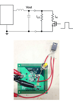
● When experiments are performed, a circuit or device the load current of which can be switched instantaneously is connected to the output of the power supply circuit for evaluation, and a helpful oscilloscope for evaluating can be used to observe the output voltage and output current.
● If the response of actual equipment is to be confirmed, for example a state is created in which a CPU or the like transitions from a standby state to full operation, and the output is similarly observed.
Important points in performing evaluations were described above; the phase margin and crossover frequency can always be inferred from an observed waveform, but this is fairly troublesome.
Recently a measurement device called a frequency response analyzer (FRA) has come into quite widespread use, and can be used to measure phase margins and frequency characteristics of extremely simple power supply circuits. Using a FRA can be very effective.。
When, in actual practice, there is no appropriate load device capable of instantaneous large-current on-off switching that can be used in experiments, a simple circuit such as that on the right in which a MOSFET is switched can be used. Of course tr and tf must be determined.
Example of Adjusting Transient
Some switching regulator ICs have a pin for adjustment of response characteristics; in many cases it is called ITH. In an application circuit indicated on the data sheet for the IC, more or less reasonable component values and configuration for a capacitor and resistor to be connected to the ITH pin under those conditions are presented. In essence, this is taken as a starting point, and adjustments are made so as to satisfy the requirements made of the circuit that is actually fabricated. It is probably best to begin by keeping the capacitor fixed and varying the resistance value.
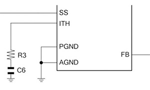
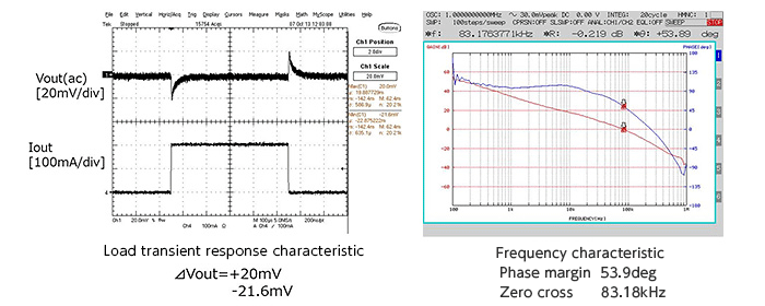
Below are oscilloscope waveforms and a frequency characteristic analysis graphs obtained using a FRA, showing the manner of change of the load transient response characteristic of the BD9A300MUV used in these examples when the capacitance of the capacitor at the ITH pin is fixed and the resistance value is adjusted.
① R3=9.1 kΩ、C6=2700 pF (Essentially an appropriate response and frequency characteristic are obtained using the recommended values)
② R3=3 kΩ、C6=2700 pF
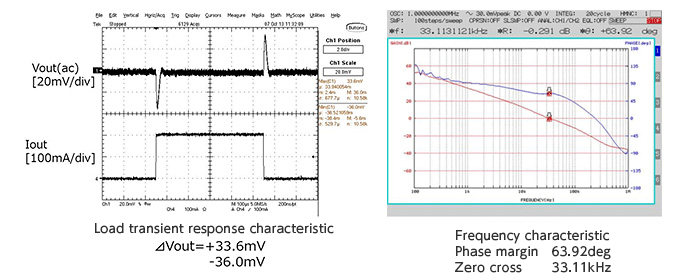
※ Upon lowering the resistance value of R3 the band was narrowed, and the load response was worsened. There are no problems with operation itself, but there is too much of a phase margin.
③ R3=27 kΩ、C6=2700 pF
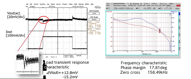
※ By raising the R3 resistance, the band is broadened and the load response is improved, but ringing occurs upon voltage fluctuation (enlarged waveform section).
The phase margin is small, and depending on scattering, abnormal oscillation may occur.
④ R3=43 kΩ、C6=2700 pF
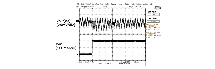
※ When the resistance value of R3 is further raised, abnormal oscillation occurs.
The above are examples of adjustment of the response characteristic using the ITH pin. In essence, voltage transients that occur in the output voltage cannot be completely eliminated, and so adjustments are made such that the response does not pose problems for operation of the circuit being supplied with current.
1. Q: What is the Advantage of Switching Regulator?
A: Switching regulators are efficient because the series elements are either fully on or off, so they hardly dissipate power. Unlike linear regulators, switching regulators can produce output voltages higher than the input voltage or of opposite polarity.
2. Q: What are Three Types of Switching Regulators?
A: Switching regulators are divided into three types: step-up, step-down and inverter regulators.
3. Q: Where are Switching Regulators Used?
A: Switching regulators are used for overvoltage protection, portable phones, video game platforms, robots, digital cameras and computers. Switching regulators are complex circuits, so they are not very popular with amateurs.
4. Q: How do I Choose a Switching Regulator?
A: Factors to consider when selecting switching regulator:
● Input voltage range. This refers to the allowable range of input voltage supported by IC.
● Output voltage range. Switching regulators usually have variable outputs
● Output current
● Operating temperature range
● Noise
● Efficiency
● Load regulation
● Packaging and dimensions.
In this share, we know the definition of load transient response, how to measure it, and learn the actual example. This skill can effectively help you detect the stability issues of a load like a switching regulator and avoid the circuit safety risks. Try to measure the transient response now! Doyou want more about the transient response measurement? Leave your comments below and tell us your ideas! If you think this share is helpful for you, don't forget to share this page!
Also Read
● How SCR Thyristor Overvoltage Crowbar Circuits Protects Power Supplies from Overvoltage?
● An Ultimate Guide to Zener Diodes in 2021
● A Complete Guide to the LDO Regulator in 2021
● Things You Should Not Miss About Facebook Meta and Metaverse
