
Products Category
- FM Transmitter
- 0-50w 50w-1000w 2kw-10kw 10kw+
- TV Transmitter
- 0-50w 50-1kw 2kw-10kw
- FM Antenna
- TV Antenna
- Antenna Accessory
- Cable Connector Power Splitter Dummy Load
- RF Transistor
- Power Supply
- Audio Equipments
- DTV Front End Equipment
- Link System
- STL system Microwave Link system
- FM Radio
- Power Meter
- Other Products
- Special for Coronavirus
Products Tags
Fmuser Sites
- es.fmuser.net
- it.fmuser.net
- fr.fmuser.net
- de.fmuser.net
- af.fmuser.net ->Afrikaans
- sq.fmuser.net ->Albanian
- ar.fmuser.net ->Arabic
- hy.fmuser.net ->Armenian
- az.fmuser.net ->Azerbaijani
- eu.fmuser.net ->Basque
- be.fmuser.net ->Belarusian
- bg.fmuser.net ->Bulgarian
- ca.fmuser.net ->Catalan
- zh-CN.fmuser.net ->Chinese (Simplified)
- zh-TW.fmuser.net ->Chinese (Traditional)
- hr.fmuser.net ->Croatian
- cs.fmuser.net ->Czech
- da.fmuser.net ->Danish
- nl.fmuser.net ->Dutch
- et.fmuser.net ->Estonian
- tl.fmuser.net ->Filipino
- fi.fmuser.net ->Finnish
- fr.fmuser.net ->French
- gl.fmuser.net ->Galician
- ka.fmuser.net ->Georgian
- de.fmuser.net ->German
- el.fmuser.net ->Greek
- ht.fmuser.net ->Haitian Creole
- iw.fmuser.net ->Hebrew
- hi.fmuser.net ->Hindi
- hu.fmuser.net ->Hungarian
- is.fmuser.net ->Icelandic
- id.fmuser.net ->Indonesian
- ga.fmuser.net ->Irish
- it.fmuser.net ->Italian
- ja.fmuser.net ->Japanese
- ko.fmuser.net ->Korean
- lv.fmuser.net ->Latvian
- lt.fmuser.net ->Lithuanian
- mk.fmuser.net ->Macedonian
- ms.fmuser.net ->Malay
- mt.fmuser.net ->Maltese
- no.fmuser.net ->Norwegian
- fa.fmuser.net ->Persian
- pl.fmuser.net ->Polish
- pt.fmuser.net ->Portuguese
- ro.fmuser.net ->Romanian
- ru.fmuser.net ->Russian
- sr.fmuser.net ->Serbian
- sk.fmuser.net ->Slovak
- sl.fmuser.net ->Slovenian
- es.fmuser.net ->Spanish
- sw.fmuser.net ->Swahili
- sv.fmuser.net ->Swedish
- th.fmuser.net ->Thai
- tr.fmuser.net ->Turkish
- uk.fmuser.net ->Ukrainian
- ur.fmuser.net ->Urdu
- vi.fmuser.net ->Vietnamese
- cy.fmuser.net ->Welsh
- yi.fmuser.net ->Yiddish
What is Half Subtractor : Working and Its Applications, K-MAP, Circuit using NAND Gate
Date:2021/10/18 21:55:58 Hits:
To process the information like light or sound from one point to other we can use analog circuits by giving proper inputs in the form of analog signals. In this process, there are chances of noise being picked up by the input analog signals and this may lead to loss in the output signal, it means whatever the input we are processing at the input level is not equal to the output stage. To, overcome these digital circuits are implemented. Digital circuit can be designed with logic gates. Logic gates are an electronic circuit which performs logical operations based upon their inputs and gives the output only a single bit, either low (Logic 0=zero voltage) or high (Logic 1=high voltage). Combinational circuits can be designed with more than one logic gate. These circuits are fast and time-independent no feedback between input and output. Combinational circuits are useful for arithmetic and Boolean operations. The best examples of the combinational circuits include Half adder, full adder, half Subtractor, full subtractor, multiplexers, demultiplexers, encoder, and decoder.What is Half Subtractor?The Half Subtractor as said above is a combinational circuit and as it name goes it is used to subtract the two bits from the input. Here the output of the subtractor is purely dependent on present inputs and it’s doesn’t depend on previous stages. Half-subtractor outputs are difference and barrow. It is similar to the arthimetic subtraction where in if the subtrahend is bigger than the minuend we would go for a borrow B =1 or else the borrow would remain zero B=0. To understand it better lets get into the truth table shown below. 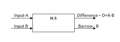 half-subtractor-block-diagramThe Truth TableThe half-subtractor truth table shows the output values as per the inputs which are applied at the input stages. The truth table is divided into two parts. The left part is denoted as the input stage and the right part denoted as the output stage.In digital circuits, input 0 and input 1 indicates logic low and logic high. As per the configuration, logic low means zero voltage, logic high means high voltage (like 5V, 7V, 12V etc). Inputs OutputsInput – AInput – BDifference -DBarrow – B 000010 1001111100Truth Table ExplanationWhen inputs A and B are zero the outputs of half-subtractor D and B are also zero.When input A is high and B is zero the difference is High i.e., 1 and Barrow is zeroWhen input A is zero and input B is high, then the outputs of D and B are high with respective.When both inputs are high the both of the outputs of half-subtractor is zero.From the above truth table, we can find the equation for the Difference (D) and Barrow (B).Equations for Difference-D: Difference is High when inputs A=1, B=0 and A=0, B=1. From this statement D = AB’+A’B = A⊕B. As per the D equation it denotes the Ex-or gate.D=A⊕BEquations for Barrow-B: Barro is high only when input A is low and B is high. From this point, the equation for Barrow B will be, B= A’BB=A’BFrom the above difference and barrow equations, we can design the half-subtractor circuit diagram using the K -MapK – MapKarnaugh map simplifies the Boolean algebra expression for the half Subtractor circuit. This is the official method for finding the Boolean algebra equation for any circuit. Let’s solve the Boolean expressions for the half-subtractor circuit using K-map.K-Map for Difference (D) and Barrow (B)
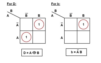 K-map for Difference (D) and Barrow (B)According to K-map first implicant is A’B and the second implicant is AB’.When we simplifying this two implicant equation, will get the simplified equation for the Difference of D.D=A’B+AB’Then, D=A⊕B. This equation is simply indicating the Ex-OR gate.To find the simplified Boolean expression for barrow B, we need to follow the same process which we followed for Difference D.Therefore, B=A’B.Half Subtractor using NAND GatesNAND gate and NOR gates are called universal gates. Here, NAND gate is called a universal gate because we can design any type of digital circuit with using of n number combinations of NAND gates. Due to this specialty, NAND gate is called a universal gate. Now, we design half-Subtractor circuit using NAND gates.
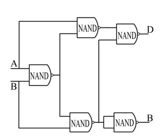 half-subtractor-implemented-with-NAND-gatesWe can design the half-subtractor circuit with five NAND gates.Consider A and B as the inputs to the first stage of NAND gate, its output again connected as one input to the second NAND gate as well as third NAND gate.As per their inputs, it gives the output and at the final stage from the NAND gates, the difference output D and barrow output B will be at their output.The final difference D output equation is D = A⊕B and barrow B equation as B=A’B.By using different combination of NAND gates for constructing the half-subtractor, the final equations of difference and barrow will be D= A⊕B and B=A’B only.Applications of Half SubtractorThere are various applications of these subtractors. Practically they are simple to analyze. Some of them are listed as follows.To subtract the numbers present in the least position at the columns these subtractors are preferred.The Arithmetic and Logic Unit (ALU) present in the processor prefers this unit for subtraction.To minimize the distortions in the sound these are used.Based on the operation required the half subtractor has the capability of increasing or decreasing the number of operators.Half subtractors are used in amplifier .While transmitting the audio signals these are used to avoid the distortions.Thus, this is all about Half subtractor circuit. In real-time conditions subtracting multiple numbers of bits cannot be done by using half-subtractors. This drawback can be overcome by using full Subtractor.
Leave a message
Message List
Comments Loading...
