
Products Category
- FM Transmitter
- 0-50w 50w-1000w 2kw-10kw 10kw+
- TV Transmitter
- 0-50w 50-1kw 2kw-10kw
- FM Antenna
- TV Antenna
- Antenna Accessory
- Cable Connector Power Splitter Dummy Load
- RF Transistor
- Power Supply
- Audio Equipments
- DTV Front End Equipment
- Link System
- STL system Microwave Link system
- FM Radio
- Power Meter
- Other Products
- Special for Coronavirus
Products Tags
Fmuser Sites
- es.fmuser.net
- it.fmuser.net
- fr.fmuser.net
- de.fmuser.net
- af.fmuser.net ->Afrikaans
- sq.fmuser.net ->Albanian
- ar.fmuser.net ->Arabic
- hy.fmuser.net ->Armenian
- az.fmuser.net ->Azerbaijani
- eu.fmuser.net ->Basque
- be.fmuser.net ->Belarusian
- bg.fmuser.net ->Bulgarian
- ca.fmuser.net ->Catalan
- zh-CN.fmuser.net ->Chinese (Simplified)
- zh-TW.fmuser.net ->Chinese (Traditional)
- hr.fmuser.net ->Croatian
- cs.fmuser.net ->Czech
- da.fmuser.net ->Danish
- nl.fmuser.net ->Dutch
- et.fmuser.net ->Estonian
- tl.fmuser.net ->Filipino
- fi.fmuser.net ->Finnish
- fr.fmuser.net ->French
- gl.fmuser.net ->Galician
- ka.fmuser.net ->Georgian
- de.fmuser.net ->German
- el.fmuser.net ->Greek
- ht.fmuser.net ->Haitian Creole
- iw.fmuser.net ->Hebrew
- hi.fmuser.net ->Hindi
- hu.fmuser.net ->Hungarian
- is.fmuser.net ->Icelandic
- id.fmuser.net ->Indonesian
- ga.fmuser.net ->Irish
- it.fmuser.net ->Italian
- ja.fmuser.net ->Japanese
- ko.fmuser.net ->Korean
- lv.fmuser.net ->Latvian
- lt.fmuser.net ->Lithuanian
- mk.fmuser.net ->Macedonian
- ms.fmuser.net ->Malay
- mt.fmuser.net ->Maltese
- no.fmuser.net ->Norwegian
- fa.fmuser.net ->Persian
- pl.fmuser.net ->Polish
- pt.fmuser.net ->Portuguese
- ro.fmuser.net ->Romanian
- ru.fmuser.net ->Russian
- sr.fmuser.net ->Serbian
- sk.fmuser.net ->Slovak
- sl.fmuser.net ->Slovenian
- es.fmuser.net ->Spanish
- sw.fmuser.net ->Swahili
- sv.fmuser.net ->Swedish
- th.fmuser.net ->Thai
- tr.fmuser.net ->Turkish
- uk.fmuser.net ->Ukrainian
- ur.fmuser.net ->Urdu
- vi.fmuser.net ->Vietnamese
- cy.fmuser.net ->Welsh
- yi.fmuser.net ->Yiddish
What is Half Adder : Circuit Diagram & Its Applications
Date:2021/10/18 21:55:58 Hits:
Half Adder is of the kind of basic digital circuit. Earlier there are various operations performed in Analog Circuits. After the discovery of digital electronics, similar operations are performed in it. The digital systems are considered to be effective and are reliable. Among the various operations, one of the most prominent operations is Arithmetic. It includes Addition, Subtraction, Multiplication, and Division. However, it is already known that it might be a computer, any electronic gadget like a calculator can perform mathematical operations. These operations are performed are consists of binary values.This is possible by the presence of certain circuits in it. These circuits are referred to as Binary Adders and Subtractors. This type of circuits is designed for the binary codes, Excess-3 codes, and other codes as well. Further Binary Adders are classified into two types. They are: Half Adder andFull AdderWhat is a Half Adder?A digital electronic circuit that functions to perform the addition on the binary numbers is defined as Half Adder. The process of addition is denary the sole difference is the number system chosen. There exists only 0 and 1 in the binary numbering system. The weight of the number is completely based on the positions of the binary digits. Among those 1 and 0, 1 is treated as the largest digit and 0 as the smaller one. The Block diagram of this adder is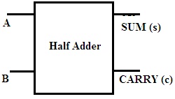 Half AdderHalf Adder Circuit DiagramA half adder consists of two inputs and produces two outputs. It is considered to be the simplest digital circuits. The inputs to this circuit are the bits on which the addition is to be performed. The outputs obtained are the sum and carry.
 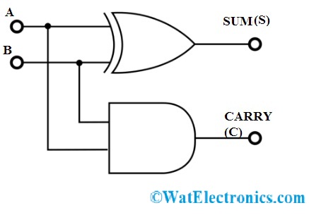 Half AdderThe circuit of this adder comprises of two gates. They are AND and XOR gates. The applied inputs are the same for both the gates present in the circuit. But the output is taken from each gate. The output of the XOR gate is referred to as SUM and the output of AND is known CARRY.Half Adder Truth TableTo obtain the relation of the output obtained to the applied input can be analyzed using a table known as Truth Table.
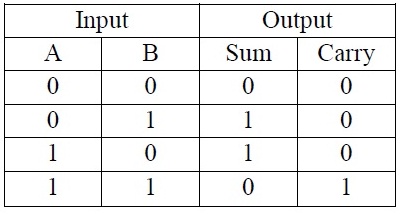 Half Adder Truth Table From the above truth table the points are evident as follows:If A=0, B=0 that is both the inputs applied are 0. Then both the outputs SUM and CARRY are 0.Among two inputs applied if anyone the input is 1 then the SUM will b e1 but the CARRY is 0.If both the inputs are 1 then the SUM will be equal to 0 and the CARRY will be equal to 1.Based on the inputs applied the half adder proceeds with the operation of addition.EquationThe equation for this type of circuits can be realized by the concepts of Sum of Products (SOP) and Products of Sum (POS). The Boolean Equation for this type of circuits determines the relation between the applied inputs to the obtained outputs.To determine the equation the k-maps are drawn based on the truth table values. It consists of two equations because two logic gates are used in it.The k-map of the carry is
 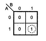 K-Map AND GateThe output equation of CARRY is obtained from the AND gate.C=A.BThe Boolean Expression for the SUM is realized by the SOP form. Hence the K-map for the SUM is
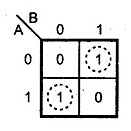 K-Map for Sum (XOR)The equation determined isS= A⊕ BApplicationsThe applications of this basic adder are as followsTo perform additions on binary bits the Arithmetic and Logic Unit present in the computer prefers this adder circuit.The combination of half adder circuits leads to the formation of the Full Adder circuit.These logic circuits are preferred in the design of calculators.To calculate the addresses and tables these circuits are preferred.Instead of only addition, these circuits are capable of handling various applications in digital circuits. Further, this becomes the heart of digital electronics.VHDL CodeThe VHDL code for the Half Adder circuity islibrary ieee;use ieee.std_logic_1164.all;entity half_adder isport(a,b: in bit; sum,carry:out bit);end half_adder;architecture data of half_adder isbeginsum<= a xor b;carry <= a and b;end data;FAQs1. What do you mean by Adder?The Digital Circuits whose sole purpose is to perform addition is known as Adders. These are the main components of ALU’s. Adders operate in addition to the various formats of numbers. The outputs of the adders are the sum and carry.2. What are the Limitations of Half Adder?The carry bit generated from the previous bit cannot be added is the limitation of this adder. To perform addition for multiple bits these circuits cant be preferred.3. How to Implement Half Adder using NOR Gate?The implementation of this type of adder can also be done by using the NOR gate. This is another Universal Gate.
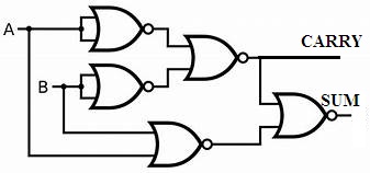 Half Adder using NOR gates4. How to Implement Half Adder using NAND Gate?The NAND gate is one of the kinds of universal gates. It indicates that any kind of circuit designing is possible by the use of NAND gates.
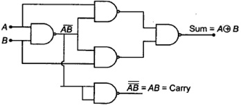 Half AdderFrom the above circuit, the carry output can be generated by applying the output of one NAND gate to the input as other NAND gate. That is nothing but familiar to the output obtained from AND gate.The output equation of SUM can be generated by applying the output of the initial NAND gate along with the individual inputs of A and B to further NAND gates. Finally, the outputs obtained by those NAND gates are applied to the gate again. Hence the output for the SUM is generated.Therefore the basic adder in the digital circuit can be designed by using various logic gates. But the multiple bits addition gets complicated and considered to be the limitation of the half adder. Can you describe which IC is used for the increment operation in any practical counters?
Leave a message
Message List
Comments Loading...
