
Products Category
- FM Transmitter
- 0-50w 50w-1000w 2kw-10kw 10kw+
- TV Transmitter
- 0-50w 50-1kw 2kw-10kw
- FM Antenna
- TV Antenna
- Antenna Accessory
- Cable Connector Power Splitter Dummy Load
- RF Transistor
- Power Supply
- Audio Equipments
- DTV Front End Equipment
- Link System
- STL system Microwave Link system
- FM Radio
- Power Meter
- Other Products
- Special for Coronavirus
Products Tags
Fmuser Sites
- es.fmuser.net
- it.fmuser.net
- fr.fmuser.net
- de.fmuser.net
- af.fmuser.net ->Afrikaans
- sq.fmuser.net ->Albanian
- ar.fmuser.net ->Arabic
- hy.fmuser.net ->Armenian
- az.fmuser.net ->Azerbaijani
- eu.fmuser.net ->Basque
- be.fmuser.net ->Belarusian
- bg.fmuser.net ->Bulgarian
- ca.fmuser.net ->Catalan
- zh-CN.fmuser.net ->Chinese (Simplified)
- zh-TW.fmuser.net ->Chinese (Traditional)
- hr.fmuser.net ->Croatian
- cs.fmuser.net ->Czech
- da.fmuser.net ->Danish
- nl.fmuser.net ->Dutch
- et.fmuser.net ->Estonian
- tl.fmuser.net ->Filipino
- fi.fmuser.net ->Finnish
- fr.fmuser.net ->French
- gl.fmuser.net ->Galician
- ka.fmuser.net ->Georgian
- de.fmuser.net ->German
- el.fmuser.net ->Greek
- ht.fmuser.net ->Haitian Creole
- iw.fmuser.net ->Hebrew
- hi.fmuser.net ->Hindi
- hu.fmuser.net ->Hungarian
- is.fmuser.net ->Icelandic
- id.fmuser.net ->Indonesian
- ga.fmuser.net ->Irish
- it.fmuser.net ->Italian
- ja.fmuser.net ->Japanese
- ko.fmuser.net ->Korean
- lv.fmuser.net ->Latvian
- lt.fmuser.net ->Lithuanian
- mk.fmuser.net ->Macedonian
- ms.fmuser.net ->Malay
- mt.fmuser.net ->Maltese
- no.fmuser.net ->Norwegian
- fa.fmuser.net ->Persian
- pl.fmuser.net ->Polish
- pt.fmuser.net ->Portuguese
- ro.fmuser.net ->Romanian
- ru.fmuser.net ->Russian
- sr.fmuser.net ->Serbian
- sk.fmuser.net ->Slovak
- sl.fmuser.net ->Slovenian
- es.fmuser.net ->Spanish
- sw.fmuser.net ->Swahili
- sv.fmuser.net ->Swedish
- th.fmuser.net ->Thai
- tr.fmuser.net ->Turkish
- uk.fmuser.net ->Ukrainian
- ur.fmuser.net ->Urdu
- vi.fmuser.net ->Vietnamese
- cy.fmuser.net ->Welsh
- yi.fmuser.net ->Yiddish
What is High Pass Filter : Working & Its Applications
Date:2021/10/18 21:55:58 Hits:
Filters are the electronic circuits that allow particular frequency components and attenuate the unwanted frequency components of an input signal. These are found in various electronic applications to allow a particular range of frequencies of a signal. Basically, filters are divided into two types based on the type of components used in designing and operation. They are Passive filters and Active filters. Depending upon the range of frequencies, filters are categorized into 4 types. They are Low Pass Filters, High Pass Filters, Band Pass Filters, and Band Stop Filters. This article describes the High Pass Filter, which can be used as both active filter and passive filter.What is a High Pass Filter?The filter has an ability to allow high-frequency components of a signal and attenuates all low-frequency components of a signal, is known as High Pass Filter. It can allow the high-frequency components greater than the cut-off frequency and rejects all other unwanted frequency components of a signal. These types of filters are found in various RF circuits and signal processing systems. In practice, this filter will allow lower frequencies of a signal, which is lower than the cut-off frequency. High Pass Filter CircuitThis circuit is the same as that of a low pass filter circuit, except that the components resistor and capacitor are interchanged as shown in the figure below.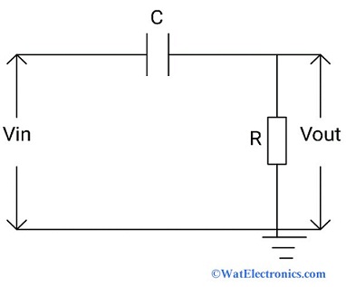 High Pass Filter CircuitTwo passive elements resistor and capacitor are connected in series combination to allow the frequencies higher than the cut-off frequency of a signal. The output voltage of a signal is obtained across the resistor by applying input voltage across the capacitor. This type of filter comes under the first order high pass filter circuit. The second-order HPF is nothing but a cascading of two RC high pass filter circuits in series. The increase in gain of the passband in the second-order HPF will be at a rate of +40dB/decade.Passive RC HPCThe passive RC high pass filter circuit can be designed in two combinations like resistor and capacitor (passive RC HPF); resistor and inductor (passive RL HPF) based on the application. The passive RC HPF is used for applications at audio or low-frequency ranges. The passive RL HPF circuits are used for applications at RF or high-frequency ranges.The high pass filter circuit is also called a passive RC high pass filter because of the usage of passive elements like a resistor and a capacitor. The main advantage is, there is no need to apply any external power supply or any amplification components.The passive RC HPF is a simple RC HPF circuit as shown in the above figure. The capacitor and resistor are connected in series where the output voltage is developed across the resistor. Due to the reactance of the capacitor, the filter allows only high frequencies of a signal greater than the cut-off frequency and blocks the lower frequencies of a signal below the cut-off frequency. CharacteristicsThese high pass filter characteristics are explained in terms of frequency response and phase shift of an output signal.Ideal CharacteristicsThe main characteristic of an HPF is, it allows all the high-frequency components greater than the cut-off frequency and attenuates all the low frequencies of a signal, which are lower than the cut-off frequency. The ideal characteristics of an HPF are shown below. The passband is referred to as the HPF allows the higher frequencies that are greater than cut-off frequency. This filter attenuates the low frequencies, which is referred to as the stopband.
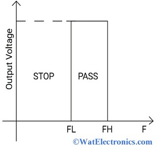 Ideal Characteristics of High Pass FilterFrequency ResponseThe frequency of an output signal is directly proportional to the gain. As the frequency increases, the gain increases. The frequency response of an RC high pass filter depends on the reactance of a capacitor.The capacitor produces the required amount of reactance or high reactance to attenuate the low frequencies of a signal, i.e., below the cut-off frequency. At low reactance of the capacitor, the RC high pass filter allows the high-frequency components of a signal i.e., greater than the cut-off frequency. But, practically, the RC high pass filter allows the low frequencies below its cut-off frequency. The gain of the RC high pass filter becomes unity when the reactance is low/zero at high frequencies. That is output voltage is the same as the given input voltage. To allow high frequencies and reject low frequencies, the capacitive reactance decreases with an increase in frequency, which results in increases in output voltage and gain. The capacitive reactance is given as,Xc = 1/2πfcWhere ‘fc’ = cut-off frequency in Hz‘Xc’= capacitive reactanceThe frequency response and phase shift characteristics of an RC high pass filter are shown below.
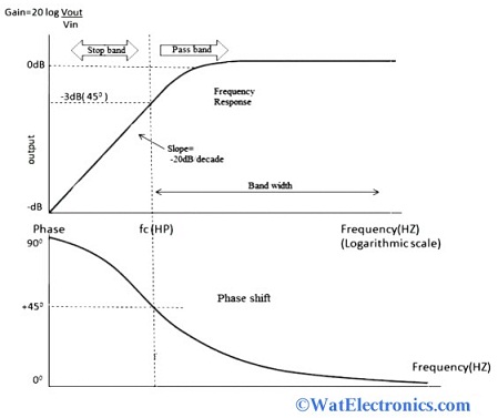 RC HPF CharacteristicsFrom the figure, we can observe that the low frequencies are blocked/rejected and increase the output voltage by +20dB/decade when the frequency is at the cut-off frequency and R=Xc. The RC high pass filter allows the high frequencies (from cut-off frequency to infinity) when the output voltage is 0.7071 or 70.71% of its input voltage i.e., at -3dB input and output levels (by calculating 20 log Vout/Vin). That means the frequency response of an HPF is, high-frequency signals are allowed from cut-off frequency to infinity.At the cut-off frequency, the phase shift of the input signal and output signal are the same i.e., at 45°. When the frequency of a signal is greater than the cut-off frequency, the phase angle is Zero. That means the output signal is in phase with respect to the input signal at high frequencies.The time taken to charge and discharge of a capacitor is expressed in the form of the time constant, denoted by ‘τ’. The time constant of an RC high pass filter is given asτ = RC = 1/2πfcω = 1/τ = 1/RCThe cut-off frequency of an RC HPF is given as,fc= 1/2πRCThe phase shift of an RC HPF is given asΦ=tan-1 (1/2πfRC)Where ‘fc’ = cut-off frequency in Hz‘f’ = operating frequency in Hz‘R’ = value of resistance in ohms‘C’= value of the capacitor in FaradsHigh Pass Filter using Op-AmpThe high pass filter using op-amp is very easy to design and implement because it uses limited no. of electronic components and removes noise and hum. The circuit diagram of the high pass filter using op-amp is shown below. The passive RC HPF is connected to the non-inverting op-amp for amplification and voltage gain control.
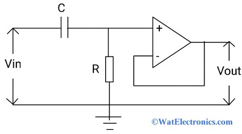 High Pass Filter using Op-AmpThe output is limited by the open-loop characteristics of the op-amp. The output of the RC HPF is applied to an op-amp for the amplification and control of the voltage gain of the output signal.The voltage gain of the high pass filter using Op-amp is given asAᵥ= Vout/Vin=Af(f/fc)/√(1+(f/fc)2)Where Av= voltage gain in dB= 1+R2/R1Af = passband gainfc= cut-off frequency in Hzf = operating frequency in HzWhen f < fc (low frequencies), then Vout/Vin < AfWhen f = fc ( at cut-off frequency), then Vout/Vin=Af/2 ^½ = 0.7071AfWhen f > fc (high frequencies), then Vout/Vin = AfThe closed-loop bandwidth of the Op-amp determines the highest frequency of the HPF, which has the constant passband gain Af.The magnitude of the voltage gain is given asAv(dB) = 20 log (Vout/Vin)-3dB = 20 log (0.707 Vout / Vin)Active High Pass FilterIf the RC high pass filter is connected to the active element like op-amp to allow the high frequencies and rejects the low frequencies, then it is called an active HPF. The frequency response and phase shift of the active HPF are the same as the RC HPF. The purpose of the active high pass filter is to control the voltage gain and amplify the output signal. The circuit diagram of the active high pass filter for amplification is shown below.
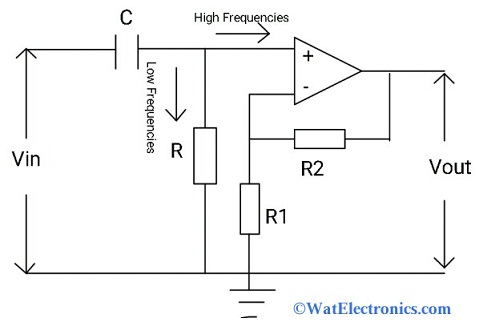 Active HPF for AmplificationThe RC HPF circuit is connected to the non-inverting op-amp. The output and the cut-off frequency of the passive high pass filter is controlled by the op-amp. Where the bandwidth and gain characteristics of op-amp determine the cut-off frequency. This type of filter acts as a bandpass filter. The op-amp increases the amplitude of the output signal and the output voltage gain of the passband is given as 1+R2/R1, which is the same as the low pass filter.Transfer FunctionTo derive the high pass filter transfer function, we will consider a passive RC HPF circuit as shown above.From the above circuit,Vo = output voltage across the resistorVi = input voltage applied across the capacitorBy taking the Laplace Transform at both input and output side,H(s)=Vₒ(s)/Vᵢ(s)H(s)=R/(R+(1/sC))The above equation becomes,H(s)=sCR/(1+sCR)By substituting s=jw in the above equationH(jω)=jωCR/(1+jωCR)Then the equation becomesThe magnitude of the HPF transfer function is represented as|H(jω)|=ωCR/√(1+(ωCR)^2 )If ω = 0, then the HPF transfer function = 0If ω = 1/CR, then the HPF transfer function = 0.707If ω = infinity, then the HPF transfer function = 1Hence the above transfer function characteristics show that the passive RC high pass filter can allow the high frequencies from cut off frequency to infinity. i.e., varies from 0 to 1 if ω varies from 0 to infinity.Butterworth HPFThe Butterworth high pass filter is one of the types of HPFs, that provides flat frequency response in the passband. Due to its flat frequency response, there will be no ripples. It is also known as a flat-flat filter, used in various applications where the closed-loop gain of the passband is unity. The circuit diagram and frequency response of the first-order Butterworth high pass filter is shown below. These are very easy, and simple to design.
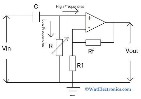 Butterworth HPFThe gain increases at the rate of +20dB/decade for the first order Butterworth HPF and while for the second-order Butterworth HPF, it will be +40dB/decade.
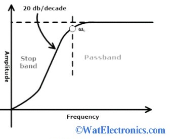 Butterworth HPF CharacteristicsApplicationsThe applications of high pass filters areSpeakers for amplifying signalsImage processingUsed in amplifying DC current and for AC couplingControl systems and audio processing systems.DSL splitters in telephonesRF applicationsThus, this is all about an overview of high pass filter (both active and passive type)- definition, circuit, Butterworth HPF, HPF using Op-amp, and its applications. Here is a question for you, “What are the advantages and disadvantages of High Pass Filters?”
Leave a message
Message List
Comments Loading...
